HVAC / Refrigeration Components
Danfoss Electronic Unit for BD35/50F Compressors User Manual
Quick guide for Danfoss Electronic Units (101N0210, 101N0220, 101N0240, 101N0300, 101N0320) for BD35/50F compressors. Includes wiring, installation, battery protection, and troubleshooting.
Table of contents
Manual images
Click an image to enlargeQuick Guide
This document provides installation and operation instructions for Danfoss electronic units used with BD35 and BD50F compressors. These units are dual-voltage devices (12V/24V) and include built-in thermal protection. The guide covers wiring, battery protection, thermostat connection, fan control, and troubleshooting via LED error codes.
Installation and Wiring
The electronic unit must be mounted directly on the compressor by snapping the cover over the screw head. Connect the terminal plug from the electronic unit to the compressor terminal.
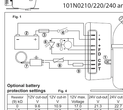
- Power Supply: Connect directly to battery poles. Connect plus to + and minus to -. The unit is protected against reverse polarity.
- Fuse: A fuse must be installed in the + cable as close to the battery as possible. Use a 15A fuse for 12V circuits and a 7.5A fuse for 24V circuits.
- Main Switch: If used, it must be rated for a minimum of 20A.
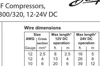
- Wire Dimensions: Refer to the wire dimension table to ensure correct gauge based on the distance between the battery and the electronic unit to prevent voltage drops.
Power Supply and Battery Protection
The compressor stops and restarts based on voltage limits measured at the + and - terminals. Standard settings are provided for 12V and 24V systems. Optional settings can be configured by connecting a resistor between terminals C and P. In solar applications without a battery, a 220 kΩ resistor is recommended. In AEO (Adaptive Energy Optimizing) speed mode, the compressor adapts its speed to cooling demand within a voltage range of 9.6V to 31.5V.
Thermostat and Fan Connections
- Thermostat: Connect the thermostat between terminals C and T. Without a resistor, the compressor runs at a fixed speed of 2,000 rpm (for 101N0210/220/240). Models 101N0300/320 adjust speed automatically based on cooling demand.
- Fan: A fan can be connected between terminals + and F. The output is regulated to 12V, so a 12V fan must be used regardless of whether the system is 12V or 24V.
Compressor Speed Control
Fixed compressor speeds between 2,000 and 3,500 rpm can be obtained by installing a resistor between terminals C and T to adjust the control circuit current. Refer to the resistor value table to select the appropriate resistor for the desired motor speed.
Troubleshooting and LED Codes
An optional 10mA LED can be connected between terminals + and D. If an operational error occurs, the LED will flash a specific number of times every 4 seconds:
- 1 Flash: Battery protection cut-out (voltage outside limits).
- 2 Flashes: Fan over-current cut-out (fan load > 1A peak).
- 3 Flashes: Motor start error (rotor blocked or differential pressure > 5 bar).
- 4 Flashes: Minimum motor speed error (system overloaded, motor cannot maintain 1,850 rpm).
- 5 Flashes: Thermal cut-out (system overloaded or high ambient temperature).
Manufacturer information
Danfoss A/S
Practical help
Common problems
LED flashes 5 times
Thermal cut-out: The refrigeration system is overloaded or the ambient temperature is too high.
LED flashes 4 times
Minimum motor speed error: System is too heavily loaded; motor cannot maintain 1,850 rpm.
LED flashes 3 times
Motor start error: Rotor is blocked or differential pressure in the refrigeration system is too high (>5 bar).
LED flashes 2 times
Fan over-current cut-out: The fan is drawing more than 1A peak.
LED flashes 1 time
Battery protection cut-out: Voltage is outside the designated cut-out setting.
Before use
- Verify battery voltage (12V or 24V).
- Install a fuse in the + cable (15A for 12V, 7.5A for 24V).
- Ensure wire dimensions match the distance between battery and unit (see Fig 2).
- Connect directly to battery poles (+ to +, - to -).
- Use a 12V fan for the fan output.
- Ensure main switch is rated for at least 20A.
Specs in practice
- Dual Voltage
- The unit automatically supports both 12V and 24V power supply systems.
- Max Ambient Temp
- The electronic unit should not be operated in environments exceeding 55°C.
Images and diagrams
- Fig 1: Wiring diagram showing connections for battery, switch, fuse, thermostat, fan, and LED.
- Fig 2: Table specifying required wire gauge based on cable length for 12V and 24V operation.
- Fig 4: Table for optional battery protection settings using resistors.
- Fig 5: Table for selecting resistors to achieve specific fixed compressor speeds.
Model compatibility
- Compatible with BD35F and BD50F compressors.
- Models 101N0300 and 101N0320 support AEO speed mode.
- Fan must be 12V regardless of system voltage.

Manual page author
Emily Carter
User documentation editor
Prepares concise manual descriptions and highlights the most useful setup, operation, and maintenance information for readers.