HVAC / Refrigeration Components
User Manual for Danfoss 101N0280 High Speed Electronic Unit
Quick guide for the Danfoss 101N0280 High Speed Electronic Unit. Includes installation instructions, wiring diagrams, battery protection settings, and troubleshooting error codes.
Table of contents
Manual images
Click an image to enlargeQuick guide from the manual
The Danfoss 101N0280 is a dual-voltage electronic unit designed for BD compressors, compatible with both 12V and 24V systems. It features built-in thermal protection and supports optional battery protection settings, thermostat control, and fan connectivity. Always ensure the unit is connected directly to the battery poles and that appropriate fuses are installed.
Installation
To install the electronic unit:
- Connect the terminal plug from the electronic unit to the compressor terminal.
- Mount the electronic unit onto the compressor by snapping the cover over the screw head.
- Ensure the unit is installed in a location where the ambient temperature does not exceed 55°C.
Power Supply and Wiring
Proper power connection is critical for operation:
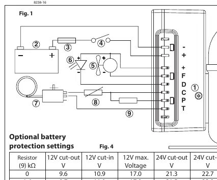
- Direct Connection: The unit must be connected directly to the battery poles (+ and -).
- Fuse Requirements: A fuse must be mounted in the positive (+) cable as close to the battery as possible. Use a 30A fuse for 12V systems and a 15A fuse for 24V systems.
- Main Switch: If a main switch is used, it must be rated for a minimum of 30A.
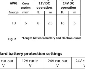
- Wire Dimensions: Observe the wire dimensions specified in the manual (10 AWG / 6 mm²) to prevent voltage drops.
Battery Protection
The compressor stops and restarts based on voltage limits measured at the terminals. Standard settings are pre-configured for 12V and 24V systems. Optional settings can be configured by connecting a resistor between terminals C and P.
Thermostat and Fan
- Thermostat: Connect the thermostat between terminals C and T. The unit will adjust compressor speed based on cooling demand.
- Fan: A fan can be connected between terminals + and F. Note that the output is regulated to 12V, so a 12V fan must be used regardless of whether the system is 12V or 24V. The fan output supports a continuous current of 0.5A.
Troubleshooting
An optional 10mA LED can be connected between terminals + and D to indicate operational errors. The LED flashes a specific number of times to identify the issue:
- 1 Flash: Battery protection cut-out (voltage outside settings).
- 2 Flashes: Fan over-current cut-out (fan draws >1A peak).
- 3 Flashes: Motor start error (rotor blocked or differential pressure >5 bar).
- 4 Flashes: Minimum motor speed error (system overloaded, cannot maintain 2,450 rpm).
- 5 Flashes: Thermal cut-out (system overloaded or ambient temperature too high).
Manufacturer information
Danfoss A/S
Practical help
Common problems
LED flashes 1 time
Battery protection cut-out. Check if the voltage is outside the cut-out setting.
LED flashes 2 times
Fan over-current cut-out. The fan is drawing more than 1A peak; check fan specifications.
LED flashes 3 times
Motor start error. The rotor is blocked or the differential pressure in the refrigeration system is too high (>5 bar).
LED flashes 4 times
Minimum motor speed error. The system is too heavily loaded to maintain the minimum speed of 2,450 rpm.
LED flashes 5 times
Thermal cut-out. The refrigeration system is overloaded or the ambient temperature is too high.
Before use
- Verify the system voltage (12V or 24V).
- Install a 30A fuse for 12V systems or a 15A fuse for 24V systems.
- Ensure wire dimensions are 10 AWG / 6 mm².
- Connect the unit directly to the battery poles.
- Ensure the ambient temperature is below 55°C.
- If using a fan, ensure it is a 12V fan.
Specs in practice
- Max Voltage (12V system)
- 17V
- Max Voltage (24V system)
- 31.5V
- Max Ambient Temperature
- 55°C
Images and diagrams
- Fig 1: Wiring diagram showing connections for battery, thermostat, fan, and LED.
- Fig 2: Wire dimension table based on distance from battery.
- Fig 3: Standard battery protection voltage cut-out/cut-in settings.
- Fig 4: Optional battery protection settings using a resistor.
- Fig 5: Compressor speed settings based on resistor values.
Model compatibility
- The unit is dual voltage (12V/24V).
- Fan output is always 12V, regardless of system voltage.
- Compatible with BD compressors.

Manual page author
David Miller
Documentation analyst
Organizes user manual content into clear summaries, with attention to model details, product context, and everyday usability.