Home / Security
Installation Guide for Danfoss Aero & Aveo Tamper Shells
Step-by-step installation instructions for Danfoss Aero and Aveo tamper shells. This guide covers mounting procedures for standard RAV and RAVL connections and configurations with remote sensors.
Table of contents
Quick guide
This document provides installation instructions for Danfoss Aero and Aveo tamper shells, which are designed to prevent unauthorized adjustment of radiator thermostats. The guide covers two main installation scenarios: standard tamper shell mounting and installation for units equipped with a remote sensor. Ensure you have the correct part number for your specific RAV or RAVL connection type before beginning.
Installation of tamper shells
Follow these steps to install the tamper shell on your thermostat:
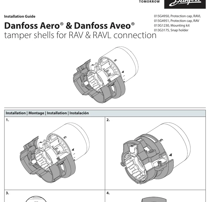
- Align the tamper shell components with the thermostat body.
- Press the shell parts together around the thermostat until they snap into place.
- Use a small screwdriver to secure the locking mechanism on the side of the shell.
- Verify that the shell is firmly attached and the thermostat dial is protected.
Installation with remote sensor
If your setup includes a remote sensor, follow these steps:
- Mount the snap holder to the wall or desired surface.
- Click the remote sensor unit into the snap holder.
- Route the sensor cable and ensure the tamper shell is properly fitted over the thermostat body as described in the standard installation section.
Compatibility and parts
The tamper shells are compatible with RAV and RAVL connections. The following parts are referenced in this guide:
- 015G4950: Protection cap for RAVL connection
- 015G4951: Protection cap for RAV connection
- 013G1230: Mounting kit
- 013G3175: Snap holder
Manufacturer information
Danfoss A/S
Practical help
Common problems
Shell does not snap into place
Ensure the shell components are correctly aligned with the grooves on the thermostat body before applying pressure.
Difficulty securing the lock
Use a small, flat-head screwdriver to gently engage the locking tab on the side of the shell.
Before use
- Identify your thermostat connection type (RAV or RAVL).
- Select the correct protection cap model (015G4950 for RAVL or 015G4951 for RAV).
- Ensure the thermostat is fully installed on the valve.
- Have a small screwdriver available for the final locking step.
Images and diagrams
- The diagrams illustrate the snap-fit mechanism where the two halves of the shell enclose the thermostat dial.
- The remote sensor diagram shows the mounting bracket installation followed by the sensor clicking into place.
Model compatibility
- Designed specifically for Danfoss Aero and Aveo series.
- Compatible with RAV and RAVL valve connections.

Manual page author
Emily Carter
User documentation editor
Prepares concise manual descriptions and highlights the most useful setup, operation, and maintenance information for readers.