HVAC / Parts & Accessories
Danfoss Solenoid Coil 018F6857 Installation Instructions
Installation guide for Danfoss Solenoid Coil 018F6857. Includes wiring diagrams, torque specifications, IP ratings, and safety guidelines for proper setup and maintenance.
Table of contents
Manual images
Click an image to enlargeQuick Guide
This document provides installation instructions for Danfoss Solenoid Coils (Types BB, BG, BQ, BT, BU, BY, and BN). Ensure that only qualified personnel perform installation or maintenance. Always disconnect the power supply before dismounting the coil. Avoid exposure to alkaline conditions; neutral conditions are recommended.
Installation Types
The solenoid coils support four primary connection types:
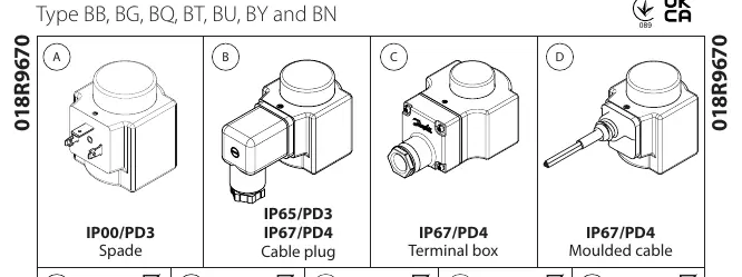
- Type A: Spade connection (IP00/PD3)
- Type B: Cable plug connection (IP65/PD3 or IP67/PD4)
- Type C: Terminal box connection (IP67/PD4)
- Type D: Moulded cable connection (IP67/PD4)
Installation and Wiring
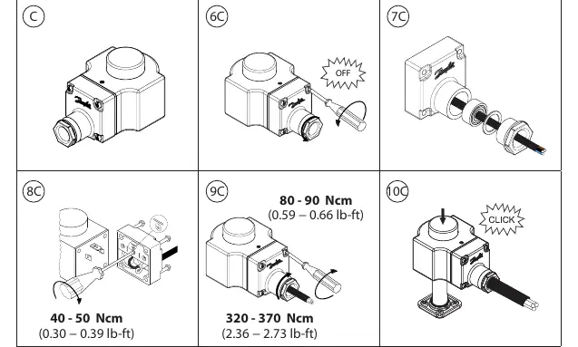
Follow the specific steps for your connection type (B or C) as detailed in the diagrams. Ensure proper torque is applied during assembly to maintain the integrity of the connection:
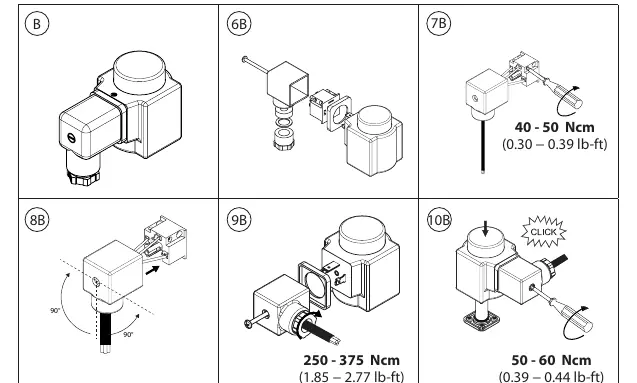
- Type B (Cable Plug): Follow the sequence for wiring and securing the plug. Ensure torque settings of 40-50 Ncm for the cable gland and 250-375 Ncm for the plug assembly.
- Type C (Terminal Box): Follow the sequence for wiring the terminal box. Ensure torque settings of 40-50 Ncm for the cable gland and 320-370 Ncm for the terminal box assembly.
Technical Specifications
- Class of Protection: Class I
- Ambient Temperature: Refer to the 'Tambient' marking on the coil.
- Impulse Withstand Voltage: 4.0 kV (for most configurations at altitude <4000m).
- Overvoltage Category: III
- Cable Requirements (Terminal Box): Suitable for cable diameters ø6.6 - ø11 mm (0.26 - 0.43 in) and conductor sizes 0.75 - 1.5 mm² (21 - 15 AWG).
- Moulded Cable: Size ø6.6 mm (0.26 in) with 3 x 0.75 mm² conductors.
Safety and Maintenance
- Power Disconnection: Always disconnect power before dismounting the coil.
- Surface Temperature: Independently mounted controls must be sealed off if the coil temperature exceeds 85°C.
- Cable Replacement: The supply cord for moulded cable versions cannot be replaced. If the cord is damaged, the entire control must be discarded.
- Plugs: Plugs can be removed and mounted a maximum of 10 times.
- Environmental: Only non-conductive pollution should be present, though temporary conductivity due to condensation may occur.
Manufacturer information
Danfoss A/S
Practical help
Common problems
Coil temperature exceeds 85°C
Independently mounted controls must be sealed off to prevent overheating issues.
Damaged supply cord (moulded cable)
The supply cord cannot be replaced; the control must be discarded if the cord is damaged.
Incorrect installation or maintenance
Only qualified personnel are permitted to install or maintain this product.
Before use
- Disconnect power before dismounting the coil.
- Verify the environment is free from alkaline conditions.
- Check that the cable diameter is between 6.6 mm and 11 mm for terminal box connections.
- Ensure the conductor size is 0.75 - 1.5 mm² for terminal box connections.
- Confirm the IP rating requirements for your specific application.
Specs in practice
- Impulse withstand voltage
- The maximum voltage spike the coil can withstand (4.0 kV).
Images and diagrams
- Type A: Spade connection diagram.
- Type B: Cable plug connection and wiring sequence.
- Type C: Terminal box connection and wiring sequence.
- Type D: Moulded cable connection overview.
Model compatibility
- Compatible with various Danfoss solenoid coil types (BB, BG, BQ, BT, BU, BY, BN).
- Not suitable for alkaline environments.
- Plugs are rated for a maximum of 10 removal/mounting cycles.

Manual page author
David Miller
Documentation analyst
Organizes user manual content into clear summaries, with attention to model details, product context, and everyday usability.