Hvac / Heat Pumps
Installation Guide for Danfoss HRB and HFE Coupling Accessories
A comprehensive installation guide for Danfoss HRB and HFE coupling accessories. Includes kit selection, valve alignment, and step-by-step actuator mounting instructions.
Table of contents
Manual images
Jump to the sectionQuick guide from the manual
This document provides instructions for installing coupling accessories for Danfoss HRB and HFE valves. Proper installation ensures correct operation of the actuator with the valve. Always verify your specific valve model against the compatibility list before beginning installation.
Kit Selection
Identify the correct kit based on your valve model:
- 082G4235: Compatible with HRB 3 and HRB 4 valves.
- 082G4230: Compatible with HFE 3, HFE 4, HRE 3, and HRE 4 valves.
Valve Alignment
Before mounting the actuator, the valve must be set to the correct position:
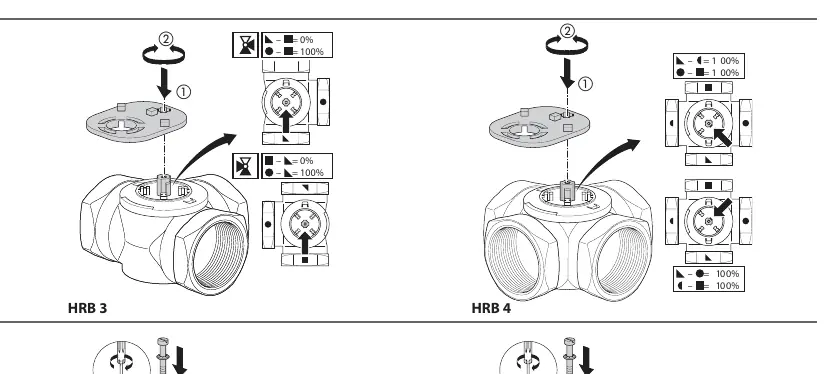
- Check the valve position indicator.
- For HRB 3 and HRB 4 valves, ensure the valve is aligned to the 0% or 100% position as required by your system configuration.
- Use the provided diagrams to verify the alignment marks on the valve stem and body.
Installation Procedure
- Prepare the Actuator: Set the actuator scale according to the requirements shown in the manual.
- Align the Valve: Ensure the valve is in the correct position (0% or 100%) as indicated in the alignment diagrams.
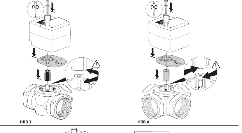
- Assemble: Place the coupling onto the valve stem.
- Mount: Secure the actuator onto the valve assembly. Ensure all components are seated correctly and the coupling is fully engaged.
- Final Check: Verify that the actuator moves freely and the valve position corresponds to the actuator setting.
Manufacturer information
Danfoss A/S
Practical help
Common problems
Incorrect kit selection
Verify your valve model number (e.g., HRB 3, HFE 4) against the compatibility table in the manual before starting.
Valve not aligned correctly
Ensure the valve is set to the 0% or 100% position before attempting to mount the actuator.
Before use
- Identify your valve model (HRB or HFE series).
- Select the correct kit (082G4235 or 082G4230).
- Verify the valve position (0% or 100%).
- Ensure the actuator scale is set correctly.
Images and diagrams
- The kit selection table helps match the valve model to the correct accessory kit.
- Step 2 diagrams illustrate the required valve alignment positions (0% vs 100%).
- Step 3 diagrams show the physical assembly order of the coupling and actuator.
Model compatibility
- Kit 082G4235 is specific to HRB 3 and HRB 4.
- Kit 082G4230 is specific to HFE 3, HFE 4, HRE 3, and HRE 4.
- Valve models HRB 3, HRB 4, HRE 3, and HRE 4 produced after 2008 are supported.

Manual page author
David Miller
Documentation analyst
Organizes user manual content into clear summaries, with attention to model details, product context, and everyday usability.