Hvac / Heat Pumps
Installation Guide for Danfoss TR6 Thermostatic Expansion Valve
A comprehensive installation and setup guide for the Danfoss TR6 thermostatic expansion valve. Includes critical instructions on flow direction, brazing temperature limits, bulb placement, and superheat adjustment procedures.
Table of contents
Manual images
Jump to the sectionQuick guide from the manual
The Danfoss TR6 is a thermostatic expansion valve designed for specific refrigerants. Key operational requirements include:
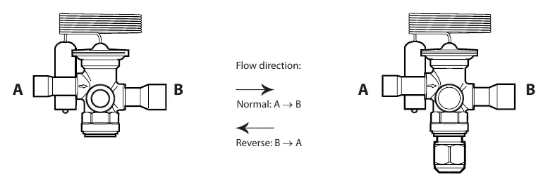
- Flow Direction: Normal flow is A to B (100% capacity). Reverse flow B to A is possible at 80% capacity.
- Max Working Pressure: 49 bar / 711 psig.
- Compatibility: Suitable for R22/R407C, R410A, R32, and R454B.
Installation and brazing
Proper installation is critical to prevent damage to the valve components.
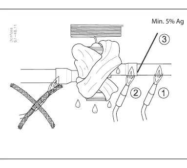
- Brazing: Use a minimum of 5% Ag (silver) content for brazing.
- Temperature Limits: Do not exceed the maximum body and bulb temperatures during installation.
- Max Temperatures:
- R22/R407C MAH: 100 °C / 212 °F
- R410A MAH: 75 °C / 167 °F
- R410A LAH: 120 °C / 248 °F
- R32 LAH: 120 °C / 248 °F
- R454B LAH: 115 °C / 239 °F
- Short-lived peak: 150 °C / 300 °F.
Bulb placement
Correct bulb placement is essential for accurate superheat control.
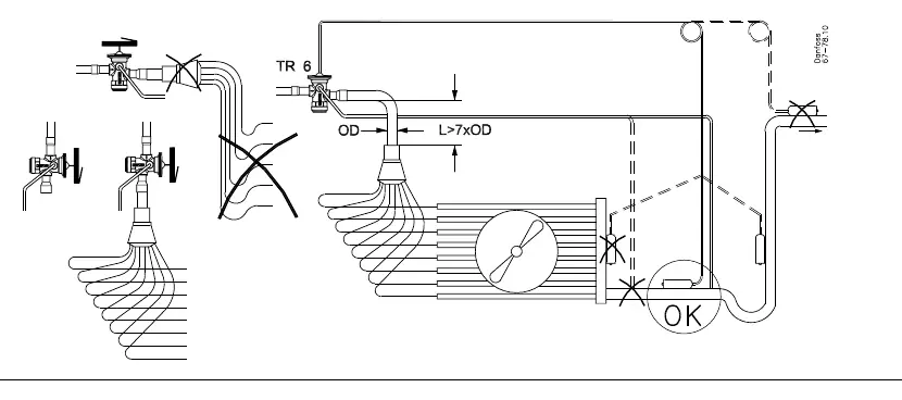
- The bulb must be mounted on a horizontal suction line.
- The distance from the evaporator outlet should be greater than 7 times the outer diameter (L > 7xOD).
- Ensure the bulb is in good thermal contact with the pipe.
Superheat adjustment
The valve allows for superheat (SS) adjustment. The factory setting varies by refrigerant.
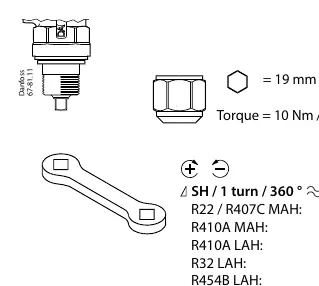
- Adjustment Tool: Use a 19 mm / 3/4 in. wrench.
- Torque: 10 Nm / 7 ft-lb.
- Procedure: Turning the adjustment screw changes the superheat. Refer to the specific refrigerant table for the number of turns required to tighten or loosen the spring.
- Superheat change per turn: Approximately 0.8 °C to 1.4 °C (1.1 °F to 2.5 °F) depending on the refrigerant.
Manufacturer information
Danfoss A/S
Practical help
Common problems
Incorrect superheat regulation
Verify bulb placement (L > 7xOD) and ensure good thermal contact with the suction line.
Valve damage during installation
Ensure brazing temperatures do not exceed the specific limits for the refrigerant type (e.g., 75°C for R410A MAH).
Incorrect flow capacity
Check flow direction; normal flow is A to B. Reverse flow (B to A) reduces capacity to 80%.
Before use
- Verify refrigerant type (R22/R407C, R410A, R32, or R454B).
- Confirm flow direction (A to B).
- Ensure brazing rod has at least 5% Ag content.
- Check that the bulb is mounted on a horizontal suction line.
- Verify the distance from the evaporator outlet is > 7xOD.
- Ensure the adjustment wrench size is 19 mm / 3/4 in.
Specs in practice
- Max Working Pressure (PS/MWP)
- 49 bar / 711 psig; do not exceed this pressure.
- SS (SuperHeat)
- The difference between the temperature of the suction gas and the saturation temperature.
Images and diagrams
- Flow direction diagram showing A to B (Normal) and B to A (Reverse).
- Brazing diagram showing the requirement for 5% Ag and temperature limits.
- Bulb placement diagram showing the L > 7xOD requirement.
- Adjustment procedure showing the use of a 19mm wrench.
Model compatibility
- Compatible with R22/R407C, R410A, R32, and R454B.
- Factory settings for superheat are specific to the refrigerant and model (MAH/LAH).

Manual page author
David Miller
Documentation analyst
Organizes user manual content into clear summaries, with attention to model details, product context, and everyday usability.