General / Other Manuals
Installation Guide for Danfoss ICAD Actuators
Quick installation and wiring guide for Danfoss ICAD actuators. Includes color codes for 1st and 2nd generation models and pinout diagrams for 4-pin and 8-pin connectors.
Table of contents
Manual images
Click an image to enlargeImportant information for installation
This document provides the necessary wiring and connection diagrams for Danfoss ICAD actuators. It is critical to identify whether your unit is a 1st generation or 2nd generation ICAD actuator, as the wiring color codes differ between these versions. Ensure all electrical connections are made according to the specified voltage requirements (24 V d.c.) and wire gauges.
Wiring color codes
The wiring requirements depend on the generation of the ICAD actuator. The cables used are 3 x 0,25 mm² (3 x 24 AWG) for power and 7 x 0,25 mm² (7 x 24 AWG) for I/O signals.
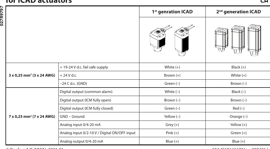
- 1st Generation ICAD: Uses specific color coding for power (White/Brown/Green) and I/O signals (White/Brown/Green/Yellow/Grey/Pink/Blue).
- 2nd Generation ICAD: Uses different color coding for power (Black/White/Brown) and I/O signals (Black/Brown/Red/Orange/Yellow/Green/Blue).
Always verify the generation of your device before connecting wires to avoid damage or malfunction.
Connector pinout diagrams
The actuators utilize two types of male connectors: a 4-pin connector and an 8-pin connector. The pinout configuration is as follows:
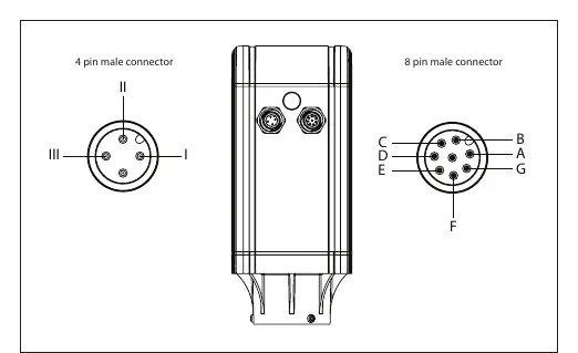
- 4-pin male connector: Used for power supply connections. Pin I is for Fail safe supply (Battery/UPS 19 V d.c.), Pin II is for Supply voltage (24 V d.c.), and Pin III is for Ground.
- 8-pin male connector: Used for Digital Output and Analogue In/Output signals. Pins A through G correspond to specific functions such as Common Alarm, ICM fully open/closed, Ground, and various Analog inputs/outputs.
Manufacturer information
Danfoss A/S
Practical help
Common problems
Incorrect wiring generation
Verify if the actuator is 1st or 2nd generation. The color codes for power and signal wires are different for each generation.
Power supply issues
Ensure the supply voltage is 24 V d.c. and the fail-safe supply is 19-24 V d.c. as specified.
Before use
- Identify the generation of the ICAD actuator (1st or 2nd).
- Confirm the wire gauge is 0,25 mm² (24 AWG).
- Verify the power supply is 24 V d.c.
- Check the pinout diagram for the 4-pin and 8-pin connectors before making connections.
Specs in practice
- 19-24 V d.c. fail safe supply
- Voltage range for the battery or UPS backup system.
- 0,25 mm² (24 AWG)
- Required cross-section area for the connection cables.
Images and diagrams
- The 4-pin connector handles power supply and fail-safe inputs.
- The 8-pin connector handles digital outputs (alarms, open/closed status) and analog I/O (0/4-20 mA, 0/2-10 V).
Model compatibility
- Wiring color codes are not interchangeable between 1st and 2nd generation ICAD actuators.

Manual page author
Emily Carter
User documentation editor
Prepares concise manual descriptions and highlights the most useful setup, operation, and maintenance information for readers.