HVAC / Thermostats & Controls
Installation Guide for Danfoss Icon2 / 24V RT Room Thermostat
Quick installation and configuration guide for the Danfoss Icon2 / 24V RT Room Thermostat. Learn how to wire the device, access the installer menu, and configure settings like floor sensor modes and cooling.
Table of contents
Quick guide from the manual
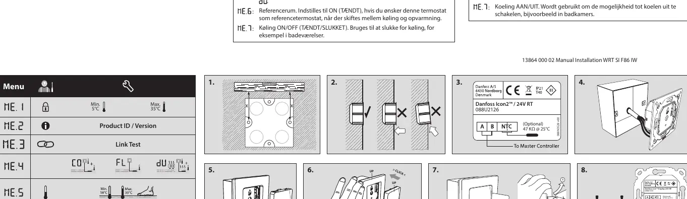
This guide covers the installation and configuration of the Danfoss Icon2 / 24V RT Room Thermostat. Installation involves following the provided figures 1 through 6, with figure 7 detailing the dismantling process. If using an optional floor sensor, ensure you use an electrical conduit (figure 8).
Installation
The thermostat can be wired in either a BUS or Star configuration. Please refer to the Master Controller Installation Guide for specific wiring details. If you are installing the optional floor sensor, it is mandatory to use an electrical conduit for the wiring.
Installer Menu
To access the settings and installer menu, follow these steps:
- Access Settings Menu: Touch and hold the menu button.
- Access Installer Menu: While in the Settings Menu, touch and hold the menu button again.
Menu Settings
The installer menu contains several configuration options identified by icons:
- Range Limitation: Set the temperature range limits for the room.
- Info/Version: Displays the product version number for identification.
- Link Test: Performs a connection test with the Master Controller. Results are shown as a percentage (0-100%). A result of 80% or higher indicates a strong connection.
- Floor Sensor Mode: Configure how the floor sensor operates:
- Comfort Mode: Uses both air and floor sensors.
- Floor Sensor Mode: The user sets the desired floor temperature.
- Dual Mode: Controls both a radiator and floor heating circuits. Floor heating ensures minimum floor temperature, while the radiator handles peak loads.
- Min/Max Floor Temp: Sets the temperature limits for the floor, applicable in Floor and Dual modes.
- Reference Room: Set to ON if this thermostat should act as the reference for switching between cooling and heating.
- Cooling ON/OFF: Enables or disables the cooling function (useful for rooms like bathrooms).
Manufacturer information
Danfoss A/S
Practical help
Common problems
Weak connection to Master Controller
Perform a Link Test. A result below 80% indicates a weak connection; check wiring and configuration.
Cooling is not functioning
Check the Cooling setting in the Installer Menu and ensure it is set to ON.
Before use
- Ensure the Master Controller is installed and powered.
- Decide on the wiring configuration (BUS or Star).
- If using a floor sensor, prepare the necessary electrical conduit.
- Verify the thermostat model is compatible with your system.
Specs in practice
- Reference Room
- Designates this specific thermostat as the master unit for switching between heating and cooling modes.
Images and diagrams
- Figures 1-6: Step-by-step physical installation guide.
- Figure 7: Instructions for dismantling the thermostat.
- Figure 8: Installation requirements for the optional floor sensor.
Model compatibility
- Requires a Master Controller for operation.
- Optional floor sensor requires an electrical conduit.

Manual page author
Emily Carter
User documentation editor
Prepares concise manual descriptions and highlights the most useful setup, operation, and maintenance information for readers.