Hvac / Thermostats Controls
Danfoss 014G0002 living connect Electronic Radiator Thermostat User Guide
Quick start guide for the Danfoss 014G0002 living connect electronic radiator thermostat, covering battery installation, mounting, system pairing, and operation.
Table of contents
Quick guide from the manual
The living connect is an electronic radiator thermostat designed for residential use within a Danfoss Link system. Before installation, ensure the thermostat display shows a flashing M. The device must be paired with a Danfoss Link CC central controller to function as part of the system.
Battery installation
- Remove the battery cover.
- Insert two AA alkaline batteries, ensuring correct orientation.
- Do not use rechargeable batteries.
- Program settings are preserved during battery replacement, but time and date settings will reset if batteries are not replaced within two minutes.
Installation
- Mount the appropriate adapter (RA or K).
- Tighten the RA adapter using a 2 mm Allen key; hand-tighten the K adapter (max 5 Nm).
- Screw the thermostat onto the adapter and tighten by hand (max 5 Nm).
- When a large M flashes on the display, press the button to fix the thermostat in place.
Adding to a system
The pairing process is performed via the Danfoss Link CC. The thermostat must be assigned to a specific room. During pairing, press and release the button; the backlight and antenna symbol will flash to indicate the device is in pairing mode.
Operation and settings
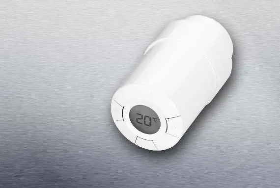
The thermostat features a digital display with buttons for navigation and temperature adjustment. While temperature is typically controlled via the Danfoss Link CC, you can manually override it at any time using the thermostat buttons. If adjusted manually, the thermostat sends a signal to the Danfoss Link CC to synchronize other thermostats in the same room.
Testing the connection
To test the connection, press the button for at least 3 seconds until M appears, then press until LI is displayed. Press the button to initiate the test. LI will disappear once the connection is established.
Safety and maintenance
The thermostat is not a toy and should be kept away from children. Do not attempt to dismantle the device, as it contains no user-serviceable parts. If error codes like E1 or E2 appear, return the unit to the distributor. Dispose of the device as electronic waste.
Manufacturer information
Danfoss A/S
Practical help
Common problems
Connection cannot be established
The alarm symbol and antenna symbol will flash. Ensure the Danfoss Link CC is in pairing mode and within range.
Error code E1, E2, etc. displayed
Do not attempt to repair; return the thermostat to the distributor.
Low battery signal
Battery icon flashes on the display. If the level is critical, the entire display will flash.
Before use
- Ensure the display shows a flashing M before starting installation.
- Use only 2 x 1.5V AA alkaline batteries (no rechargeables).
- Ensure the Danfoss Link CC central controller is ready for pairing.
- Have a 2 mm Allen key ready for RA adapter installation.
- Verify the thermostat is assigned to a room in the Danfoss Link system.
Specs in practice
- Control type
- PID (Proportional-Integral-Derivative) for precise temperature regulation.
- Transmission frequency
- 868.42 MHz, with a range of up to 30 meters.
- Temperature setting range
- Adjustable between 4°C and 28°C.
Images and diagrams
- The display shows icons for battery status, set temperature, network connection, lock, frost protection, and alarm.
- Buttons are used to navigate menus and confirm selections.
Model compatibility
- Designed for use with the Danfoss Link system.
- Requires Danfoss Link CC central controller for full functionality.

Manual page author
Emily Carter
User documentation editor
Prepares concise manual descriptions and highlights the most useful setup, operation, and maintenance information for readers.