HVAC / Refrigeration Components
Danfoss 101N0710 Electronic Unit for BD350GH Compressor
Quick guide for the Danfoss 101N0710 electronic unit for BD350GH compressors. Includes installation, wiring, battery protection settings, and error code troubleshooting.
Table of contents
Manual images
Click an image to enlargeQuick Guide
The Danfoss 101N0710 is an electronic unit designed for the BD350GH compressor. It operates on 24V DC power systems. The unit features built-in thermal protection and can be configured via the TOOL4COOL software interface. Key operational parameters, such as battery protection voltage and compressor speed, are adjustable through this interface.
Installation
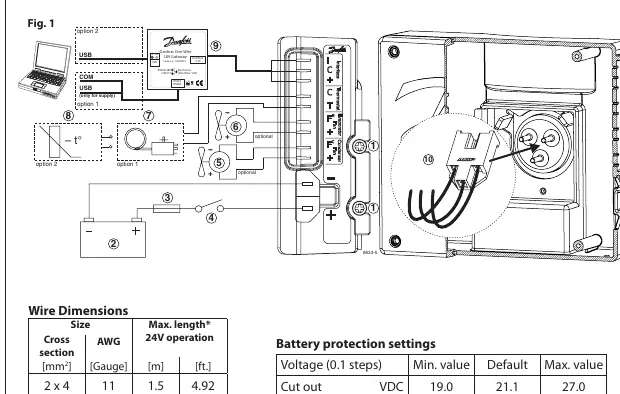
Mount the electronic unit directly onto the compressor and secure it using the two provided screws. Connect the terminal plug from the electronic unit to the compressor terminal.
Power Supply and Wiring
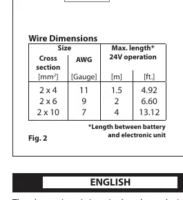
The unit must be connected directly to the battery poles. Ensure the positive wire is connected to the + terminal and the negative wire to the - terminal. To protect the installation, a 30A fuse must be installed in the positive cable as close to the battery as possible. If a main switch is used, it must be rated for at least 50A. Refer to the wire dimensions table for the required cross-section based on the cable length between the battery and the electronic unit.
Thermostat and Speed Settings
The thermostat connects between terminals C and T. You can use either an NTC (electrical) thermostat or a mechanical thermostat. The software allows for three modes: Auto (default), NTC, or Mechanical. When using an NTC, it is recommended to set the mode to NTC in the software. Compressor speed is factory-set to 4,000 rpm but can be adjusted between 2,500 and 4,000 rpm via the communication interface.
Fan Configuration
The unit supports an evaporator fan (connected to + and Fe) and a condenser fan (connected to + and Fc). The factory setting is for no fans and 24V operation. If fans are used, the software settings must be updated to reflect the fan usage and voltage (12V or 24V). The unit must be restarted after changing these settings.
Error Handling
If the electronic unit records an operational error, the code can be read using the TOOL4COOL software. Common errors include thermostat failure, thermal cut-out, motor speed errors, motor start errors, fan over-current, and battery protection cut-outs.
Manufacturer information
Danfoss A/S
Practical help
Common problems
Thermostat failure (Error 6)
Check if the NTC thermistor is short-circuited or disconnected.
Thermal cut-out (Error 5)
The refrigeration system is overloaded or the ambient temperature is too high.
Minimum motor speed error (Error 4)
The system is too heavily loaded; the motor cannot maintain the minimum speed of 1,850 rpm.
Motor start error (Error 3)
The rotor is blocked or the differential pressure in the refrigeration system is too high.
Fan over-current cut-out (Error 2)
The fan load exceeds 1.8A peak.
Before use
- Verify power supply is 24V DC.
- Install a 30A fuse in the positive cable near the battery.
- Ensure wire cross-sections match the cable length requirements (Fig 2).
- Connect the unit directly to the battery poles.
- Mount the unit securely to the compressor with two screws.
- Configure fan settings in the software if fans are connected.
Specs in practice
- Max Ambient Temperature
- 55°C.
- Factory Speed
- 4,000 rpm.
- Default Cut-out Voltage
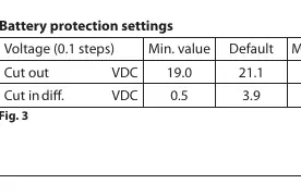
- 19.0 VDC (Cut out) / 21.1 VDC (Default).
Images and diagrams
- Fig 1 illustrates the wiring connections for the compressor, battery, thermostat, and communication gateway.
- Fig 2 provides the required wire dimensions for 24V operation based on cable length.
- Fig 3 lists the battery protection voltage settings.
- Fig 4 defines the operational error codes.
Model compatibility
- Compatible with NTC or mechanical thermostats.
- Requires TOOL4COOL software for advanced configuration.
- Supports 24V DC systems only.

Manual page author
Emily Carter
User documentation editor
Prepares concise manual descriptions and highlights the most useful setup, operation, and maintenance information for readers.