Hvac / Heat Pumps
Danfoss TQ Electronically Operated Expansion Valve User Guide
Quick guide for the Danfoss TQ electronically operated expansion valve, covering installation, orientation, technical specifications, and orifice selection.
Table of contents
Manual images
Jump to the sectionQuick guide from the manual
This document provides installation and technical specifications for the Danfoss TQ electronically operated expansion valve. It is intended for qualified personnel responsible for HVAC system integration. Key requirements include correct valve orientation, proper orifice selection based on the specific model, and adherence to torque specifications during assembly.
Installation and Mounting
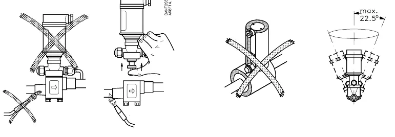
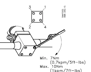
The TQ valve must be installed in the correct flow direction as indicated by the arrow on the valve body. The valve can be mounted in various orientations, but ensure the actuator is positioned to avoid moisture ingress or mechanical stress. When securing the valve, ensure the mounting bolts are tightened to a torque between 7 Nm (5 ft-lbs) and 10 Nm (7 ft-lbs).
Orifice Selection and Technical Data
The TQ valve performance depends on the correct orifice size. Refer to the provided table to match your specific code number (e.g., 068F2041) with the corresponding orifice number and required Y-dimension (0.5 mm tolerance). The valve is rated for a maximum operating pressure (MWP) of 320 psig (22 bar) and an operating temperature range of -30°C to +60°C.
System Integration
The TQ valve is designed to work with controllers such as the AKC 24P/W or EKC 315A. Ensure the distance between the valve and the evaporator inlet (L) is at least 7 times the pipe diameter (L > 7 x Ø) to ensure proper flow distribution. The system should also incorporate appropriate sensors like the AKS 21A and pressure transmitters (AKS -1-12 bar) for optimal control.
Manufacturer information
Danfoss A/S
Practical help
Common problems
Incorrect flow direction
Ensure the arrow on the valve body points in the direction of the refrigerant flow.
Improper mounting torque
Tighten mounting bolts to a range of 7 Nm to 10 Nm to prevent leaks or mechanical damage.
Incorrect orifice performance
Verify the code number against the orifice table to ensure the correct Y-dimension is maintained.
Before use
- Verify the valve code number matches the system requirements.
- Ensure the installation environment is within the -30°C to +60°C temperature range.
- Check that the flow direction arrow is correctly oriented.
- Confirm the distance L > 7 x Ø is maintained before the evaporator.
- Ensure the controller (e.g., AKC 24P/W) is compatible with the TQ valve.
Specs in practice
- MWP 320 psig
- Maximum Working Pressure the valve can safely withstand.
Images and diagrams
- The flow diagram shows the TQ valve positioned between the controller and the evaporator.
- The mounting diagrams illustrate the correct vertical and angled orientation of the actuator.
- The bolt pattern diagram shows the 4-point mounting sequence for the valve flange.
Model compatibility
- Compatible with AKC 24P/W and EKC 315A controllers.
- Designed for use with AKS 21A sensors and AKS pressure transmitters.

Manual page author
Emily Carter
User documentation editor
Prepares concise manual descriptions and highlights the most useful setup, operation, and maintenance information for readers.