Industrial / Electrical
Installation Guide for Danfoss VLT All-mode Filter MCC 201
Quick installation and setup guide for the Danfoss VLT All-mode Filter MCC 201. Includes mounting instructions, wiring diagrams, safety precautions, and technical specifications.
Table of contents
Manual images
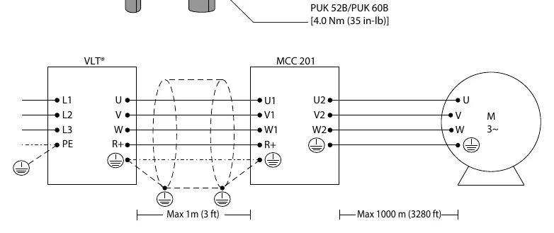
Click an image to enlargeQuick guide from the manual
The VLT All-mode Filter MCC 201 is designed to be used exclusively with Danfoss VLT drives. This guide provides essential information for safe installation, wiring, and operation. Ensure all personnel are qualified electrical engineers before attempting installation or maintenance.
Safety precautions
- Heavy load: The filter is heavy. Use the integrated lifting eyes for transport, but note that they are not aligned with the center of gravity, so the unit will not be level when lifted.
- Discharge time: Capacitors in the drive and filter remain charged after power-off. Wait for the specified discharge time (shown on the drive exterior) before servicing. Verify discharge by measuring voltage between motor phases (U2, V2, W2).
- Induced voltage: Run output motor cables separately or use shielded cables to prevent induced voltage from charging capacitors while the equipment is off.
- Electrical shock: Leakage currents exceed 3.5 mA. Ensure proper protective earth (PE) connection using reinforced conductors according to IEC 60364-5-54.
Installation and mounting
Installation location is critical for maintaining full nominal current. Ensure the following conditions are met:

- Temperature: Ambient temperature must be between -30 °C and 45 °C.
- Altitude: Maximum altitude is 1000 m without derating.
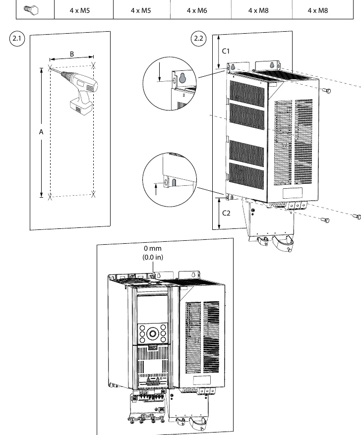
- Mounting: Mount on a solid, non-combustible surface (concrete or metal). Use 4 screws for vibration levels specified in IEC 60721-3-3:2019.
- Clearance: Provide sufficient free space above and below the filter. The filter can be side-mounted with the VLT drive with no required spacing between them.
Wiring and connections
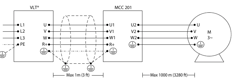
All wiring must comply with local and national regulations. Use shielded cables between the drive output and filter input. The shield connections must exhibit the lowest possible impedance; use the provided shield connection-blades from the accessory bag. Ground the filter before switching on the power using the enclosed protective earth terminal.
Technical specifications
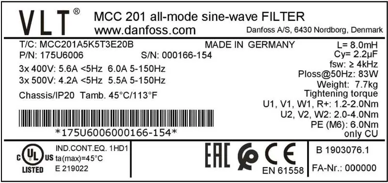
The filter is compatible with VLT HVAC Drive FC 102, Refrigeration Drive FC 103, AQUA Drive FC 202, and AutomationDrive FC 302. It features an IP20 protection rating. For detailed ratings, including current, inductance, and power loss, refer to the tables in the specifications section of the manual.
Manufacturer information
Danfoss A/S
Practical help
Common problems
High leakage currents (>3.5 mA)
Ensure the drive or filter is properly connected to protective earth (PE) using reinforced conductors.
Filter is not level when lifted
The integrated lifting eyes are not aligned with the center of gravity; this is normal behavior.
Interference in control wires
Keep control wires as short as possible and physically separate them from high-power cables.
Before use
- Verify that the supplied items match the order confirmation.
- Check the product label on the front of the filter for specific ratings.
- Ensure the mounting surface is solid and non-combustible.
- Confirm that the ambient temperature is within the -30 °C to 45 °C range.
- Ensure lifting equipment is in proper working condition.
Specs in practice
- Discharge time
- Minimum time to wait after power-off before servicing to ensure capacitors are safe.
Images and diagrams
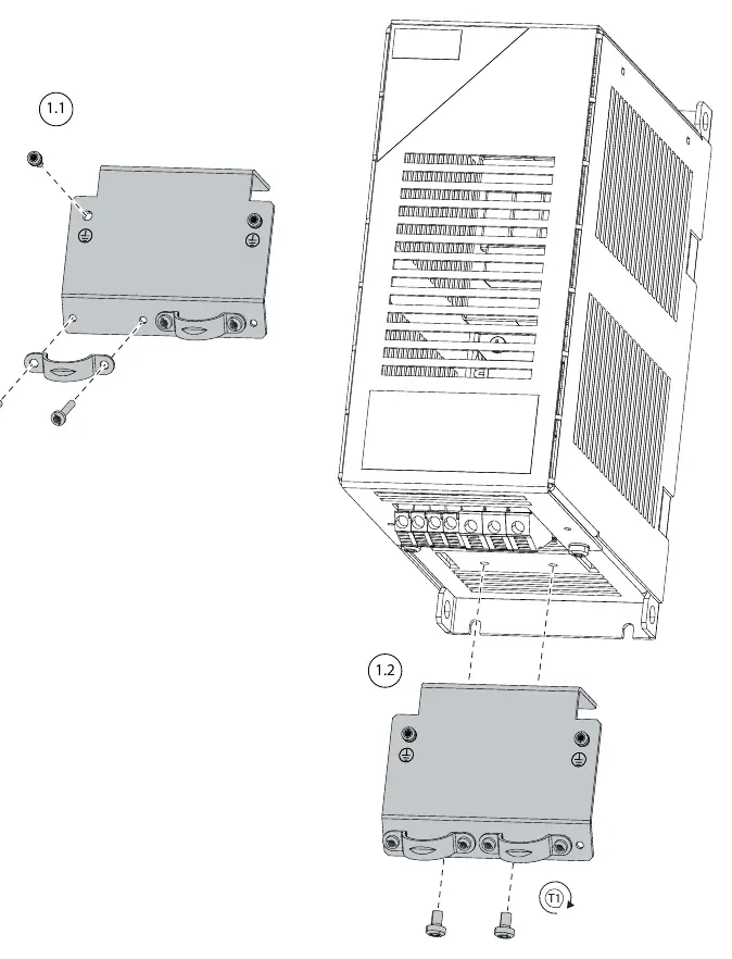
- Dimension drawings show mounting hole locations and overall dimensions for different filter models.
- Wiring diagrams illustrate the connections between the VLT drive, the MCC 201 filter, and the motor.
Model compatibility
- Compatible with VLT HVAC Drive FC 102, Refrigeration Drive FC 103, AQUA Drive FC 202, and AutomationDrive FC 302.

Manual page author
David Miller
Documentation analyst
Organizes user manual content into clear summaries, with attention to model details, product context, and everyday usability.