Tools / Welding Equipment
User Manual for Draper 230V/400V Arc Welders 71090 & 71151
Comprehensive user manual for Draper 230V/400V Arc Welders (Stock Nos. 71090 & 71151). Includes safety instructions, setup, operation, maintenance, and troubleshooting guides.
Quick answers from the manual
Quick answer
- The Draper 230V/400V Arc Welders (71090/71151) are AC welding machines designed for light repair and fabrication. They require a 16A power supply and must be properly earthed. p. 5, 9
Key actions
- Adjusting welding current p. 14
- Connecting to power p. 9
First start
- Unpack and check for damage. p. 11
- Connect ground lead and electrode holder. p. 12
Show 4 more answers Show less
Problems and fixes
Insufficient penetration
Check arc distance, increase welding current, increase wire speed.
p. 15Maintenance and reset
- Vacuum ventilation slots after use. p. 16
Technical specifications
| Parameter | Value | Meaning | Pages |
|---|---|---|---|
| Rated Voltage (71090) | 230V~50Hz | Input voltage | p. 5 |
| Rated Voltage (71151) | 230V/400V~50Hz | Input voltage | p. 5 |
| Welding current range (71090) | 60-160A | Current range | p. 5 |
| Welding current range (71151) | 100-250A | Current range | p. 5 |
Where to find it in the PDF
- Identification p. 10
- What's in the box p. 11
- Operating Instructions p. 14
Table of contents
Manual images
Click an image to enlargeQuick Guide
This manual provides essential instructions for the safe and effective use of Draper 230V/400V Arc Welders (Stock Nos. 71090 and 71151). Always ensure the machine is properly earthed and connected to a 16A power supply. Wear appropriate personal protective equipment (PPE), including welding masks, gloves, and flame-proof clothing, before starting any welding operation.

Safety Information
Electric Shock: Never touch live electrical parts. Ensure the machine is correctly earthed. Always disconnect the plug from the socket before carrying out adjustments, servicing, or maintenance. Allow 5 minutes for capacitors to discharge before removing panels.
Fumes & Gases: Welding generates hazardous fumes. Ensure adequate ventilation or use a fume extractor, especially in confined spaces.
Fire & Explosion: Clear the area of flammable materials before starting. Sparks and molten metal can cause fires; keep fire-fighting equipment nearby.
Operation
Setup: Connect the ground lead to the workpiece and the welding electrode to the electrode holder. When the electrode touches the workpiece, the circuit is complete, and the arc is produced.
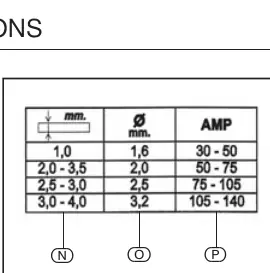
Adjusting Current: Select the welding current based on the electrode diameter and material thickness. Refer to the table on page 14 for indicative settings. Do not force the adjustment flywheel.
Thermal Cutout: If the machine is pushed beyond its performance levels, a thermal cutout will stop operation. Wait for the machine to cool down before resuming.
Maintenance
Regularly inspect and clean the machine. Keep air inlets clear to ensure proper ventilation. After use, disconnect the power and vacuum the ventilation slots. If the supply cord requires replacement, it must be performed by the manufacturer or an authorized agent.
Manufacturer information
Draper Tools
Practical help
Common problems
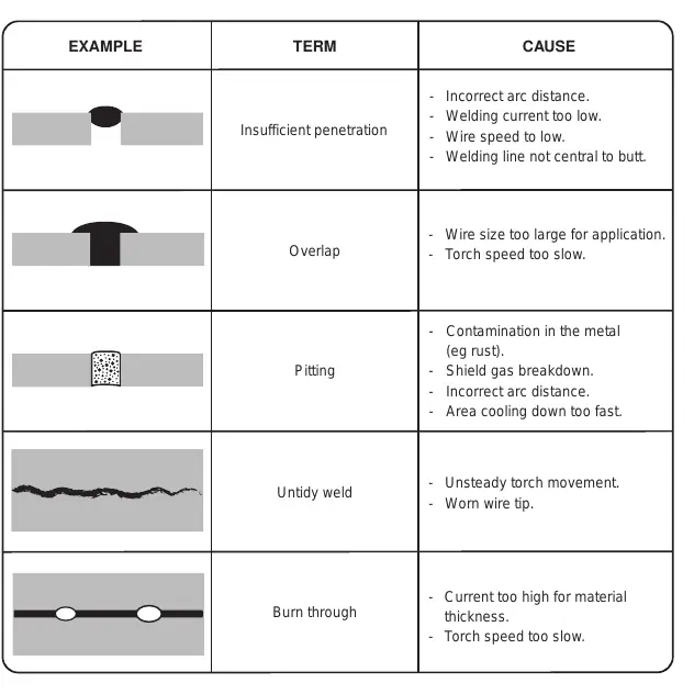
Insufficient penetration
Check arc distance, increase welding current, increase wire speed, or ensure the welding line is central to the butt.
Overlap
Use a smaller wire size or increase torch speed.
Pitting
Remove contamination (e.g., rust) from metal, check shield gas, adjust arc distance, or slow down cooling.
Burn through
Decrease current for the material thickness or increase torch speed.
Before use
- Check that the electrical supply voltage and frequency match the machine specifications.
- Ensure the machine is fitted with a delayed fuse suited to the rated current.
- Verify the machine is properly earthed (Class 1 appliance).
- Inspect all cables for damage or deteriorated insulation.
- Ensure the area is clear of flammable materials.
- Wear appropriate PPE: welding mask, gloves, and flame-proof clothing.
Show more Show less
Images and diagrams
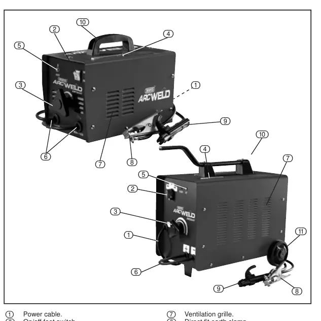
- Page 10 illustrates the identification of parts, including the on/off switch, current adjustment, and cable connections.
- Page 11 details the contents of the box for both models, including the chipping hammer, wire brush, and mask.
Model compatibility
- Model 71151 supports both 230V and 400V (requires voltage selector switch).
- Model 71090 is designed for 230V operation.

Manual page author
Michael Turner
Technical manual editor