Tools / Power Tools
User Manual for Draper 150mm & 200mm Bench Grinder
Quick guide for the Draper 150mm and 200mm Bench Grinder (05095 & 05097). Includes assembly instructions, safety guidelines, wheel replacement steps, and technical specifications.
Table of contents
Manual images
Click an image to enlargeQuick Guide from the Manual
This manual covers the operation and safety of the Draper Bench Grinder (Models 05095 and 05097). Key safety requirements include wearing eye and face protection, ensuring the machine is securely bolted to a workbench, and maintaining proper clearances for spark deflectors and tool rests. Always disconnect the power supply before performing any adjustments, maintenance, or wheel replacements.
Product Identification
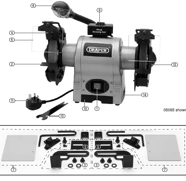
The bench grinder consists of several key components: the On/Off switch, adjustable tool rests, spark deflectors, eyeshields, a worklight, and a wheel dressing tool. Refer to the identification diagram to locate these parts before assembly.
Assembly Instructions
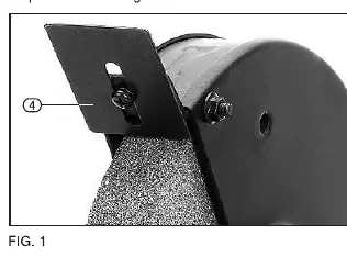
Spark Deflectors: Fit both spark deflectors to the wheel guards. Adjust them frequently to compensate for wheel wear, keeping the distance between the spark arrestor and the wheel as small as possible, not exceeding 2mm.
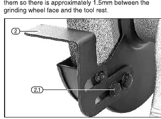
Tool Rests: Attach the tool rests to the inner edge of the wheel guards using the provided locking nuts. Adjust the position so there is approximately 1.5mm of clearance between the grinding wheel face and the tool rest.
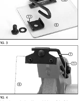
Eyeshields: Assemble the clear plastic shield to the metal rod using the provided nuts and screws. Clamp the rod to the wheel guard and tighten all fixings. Do not overtighten, as this may cause the shield to crack.
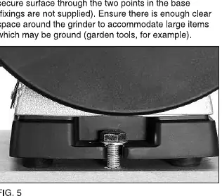
Bench Mounting: Securely bolt the bench grinder to a workbench or other stable surface using the two points in the base. Ensure there is enough clear space around the grinder for large items.
Replacing Grinding Wheels
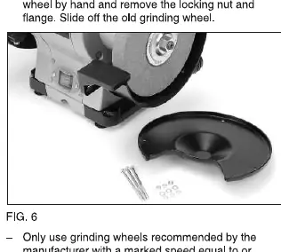
To replace a wheel, switch off and disconnect the power supply. Remove the screws and nuts holding the wheel guard, then remove the cover. Hold the other wheel by hand and remove the locking nut and flange to slide off the old wheel. Ensure the new wheel is recommended by the manufacturer, has a marked speed equal to or greater than the grinder's rated speed, and is free of damage. Test run the wheel for a reasonable time after mounting.
Operation and Use
Ensure the item to be ground is held comfortably and securely. Present the workpiece smoothly to the grinding wheel face with light, even pressure. Grind against the edge of the workpiece to avoid burrs. Never grind on the sides of the wheels. Best results are achieved when the grinder is allowed to rotate at its maximum speed.
Maintenance and Safety
Regular inspection and cleaning reduce the necessity for maintenance. Keep ventilation slots clear to prevent overheating. If the tool develops a fault, return it to your nearest distributor or contact Draper Tools. Do not dispose of power tools with domestic waste; follow local regulations for WEEE disposal.
Manufacturer information
Draper Tools
Practical help
Common problems
Excessive vibration
Ensure the grinder is securely bolted to a workbench or mounted on a vibration absorption mat (Draper Stock No. 30743).
Wheel wear
Replace grinding wheels that are worn more than 25%.
Spark gap too wide
Adjust spark deflectors to keep the distance between the spark arrestor and the wheel as small as possible (not greater than 2mm).
Before use
- Ensure the grinder is securely bolted to a workbench.
- Check that the grinding wheel is not chipped, cracked, or otherwise defective.
- Verify that the spark deflectors are adjusted to within 2mm of the wheel.
- Ensure the tool rest is adjusted to within 1.5mm of the wheel face.
- Wear appropriate eye and face protection (safety goggles, dust mask).
Specs in practice
- Rated voltage
- 230V~50Hz
- Revolutions per minute
- 2,850 RPM (no load)
- Wheel diameter (05095)
- 150mm
- Wheel diameter (05097)
- 200mm
Images and diagrams
- Fig A: Identification of parts including On/Off switch, tool rests, spark deflectors, and eyeshields.
- Fig 1: Assembly of spark deflectors.
- Fig 2: Assembly of tool rests.
- Fig 3-4: Assembly of eyeshields.
- Fig 5: Bench mounting instructions.
Model compatibility
- Use only grinding wheels recommended by the manufacturer with a marked speed equal to or greater than the grinder's rated speed.
- The left-hand grinding wheel locking nut has a left-handed thread.

Manual page author
Emily Carter
User documentation editor
Prepares concise manual descriptions and highlights the most useful setup, operation, and maintenance information for readers.