Electronics / Projector Screens
Installation and Operation Manual for Draper Premier 220V Projection Screen
Comprehensive installation and operation guide for the Draper Premier 220V electrically operated projection screen. Includes mounting instructions, electrical wiring diagrams, limit adjustments, and safety guidelines.
Quick answers from the manual
Quick answer
- The Draper Premier 220V is an electrically operated projection screen. Installation requires professional mounting and electrical wiring. Key setup steps include removing shipping brackets, mounting the case securely, connecting power, and adjusting limit switches if necessary. p. 1, 2, 3, 4
Key actions
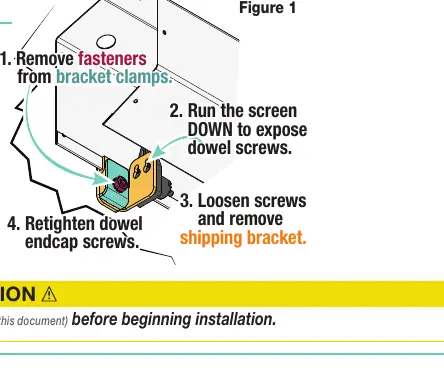
- Remove shipping brackets p. 1
- Adjust limit switches p. 4
- Adjust tab-tension p. 5
First start
- Cycle unit down and up several times to confirm satisfactory operation. p. 2
Show 4 more answers Show less
Problems and fixes
Screen limits need adjustment
Use 5/32" hex key for standard motors (clockwise decreases travel) or wall switch programming for ILT motors.
p. 4Maintenance and reset
- Reverse motor direction (ILT motors) p. 4
Technical specifications
| Parameter | Value | Meaning | Pages |
|---|---|---|---|
| Voltage | 220V AC | Operating voltage | p. 2 |
| Current Draw | .55 Amp | Electrical current consumption | p. 2 |
| Duty Cycle | On 28s / Off 4m | Operational cycle limits | p. 2 |
Where to find it in the PDF
- Shipping Brackets p. 1
- Electrical Connections p. 2, 5, 6, 7
- Installation p. 3
- Limit Adjustments p. 4
Table of contents
Manual images
Click an image to enlargeQuick Guide from the Manual
The Draper Premier 220V is an electrically operated projection screen. Important: This product is very heavy and requires professional installation. Before beginning, ensure the wall or ceiling structure is sufficient to hold the weight. Always remove shipping brackets before the first operation. The screen must be tested by cycling it up and down several times to confirm satisfactory operation.
Safety Information
- Installation and calibration should only be performed by an authorized, qualified professional.
- Electrical work must be completed by a qualified electrician.
- Do not wire motors in parallel without written permission from Draper, Inc.
- Ensure the unit is level and square during installation.
- Never leave the area while operating the unit during installation or maintenance.
- Failure to follow installation guidelines invalidates all warranties.
Installation Methods
The screen can be installed using several methods depending on the environment:
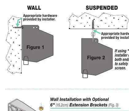
- Wall Installation: Mount through holes in the back of the endcaps using appropriate hardware (screws, toggle bolts, anchors).
- Suspended Installation: Suspend from holes in the endcaps using "S" hooks, chains, or cables. Ensure "S" hooks are crimped for safety.
- Wall Installation with Extension Brackets: Use optional 6" extension brackets if needed.
- Recessed Installation: Requires an optional Ceiling Opening Trim Kit. Suitable for acoustical drop ceilings only.
Electrical Connections
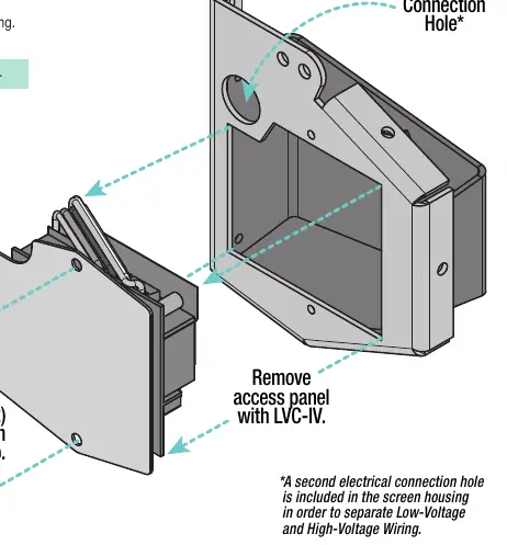
The screen operates on 220V AC, 50/60 Hz. The junction box is located inside the left endcap. Ensure all operating switches are in the "off" position before connecting power. The system includes internal wiring; the installer must connect the screen to the switch and the switch to the power supply.
Operation and Controls
The screen can be operated via:
- 220V Single Station Control: 3-position UP-OFF-DOWN switch.
- 24V Control (Optional): Requires LVC-IV unit for 3-button operation.
- Key Operated Switching: Optional key-operated power supply or 3-position key switch.
- Plug & Play: Provided with a 3-button wall switch and 10' cord.
Adjustments
Limit Adjustments
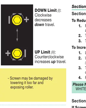
Limits are factory-set but may require adjustment. Caution: Be sure all switches are in the "off" position before adjusting. Do not allow the dowel to wrap over the roller.
- Standard/Quiet Motors: Use a 5/32" (4 mm) hex key to turn limit screws. Clockwise decreases travel; counterclockwise increases travel.
- ILT Motors: Use the wall switch to set limits. Follow the specific programming sequence provided in the manual.
Tab-Tension Adjustment
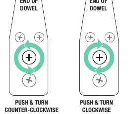
The system is factory-set. If wrinkles appear, use the adjustment screws at the end of the dowel. Push and turn clockwise to increase tension; push and turn counter-clockwise to release tension.
Dimensions
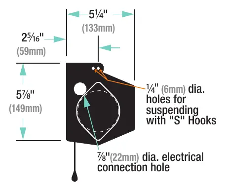
Refer to the dimensions section for detailed measurements of the case, mounting holes, and electrical connection points to ensure proper clearance and fitment.
Manufacturer information
Draper Tools
Practical help
Common problems
Screen does not operate or stops unexpectedly
Check electrical connections and ensure power is supplied. Verify that the switch is in the correct position.
Screen limits are incorrect (stops too high or too low)
Adjust the limit screws (Standard/Quiet motors) or reprogram limits using the wall switch (ILT motors) as described in the manual.
Wrinkles on the viewing surface
Adjust the tab-tension system at the ends of the dowel by pushing and turning the adjustment screws.
Screen operates in the wrong direction
For ILT motors, hold the STOP button for 3-5 seconds while in programming mode to reverse the motor direction.
Before use
- Remove shipping support brackets from bracket clamps at each end of the dowel.
- Ensure the wall or ceiling structure is strong enough to support the unit.
- Verify all hardware is installed level and square.
- Check all electrical connections before applying power.
- Cycle the unit down and up several times to confirm satisfactory operation.
Show more Show less
Specs in practice
- Power Requirements
- 220V AC, 50 Hz or 60 Hz, .55 Amp, 1 phase.
Images and diagrams
- Figure 1: Removing shipping brackets.
- Figure 2: Wall and Suspended installation methods.
- Figure 6: Limit adjustment screw locations.
- Figure 8: ILT motor wiring and programming.
Model compatibility
- Optional LVC-IV required for 24V control.
- Optional 6" extension brackets available for wall installation.
- Optional Ceiling Opening Trim Kit required for recessed installation.
- Do not wire motors in parallel.

Manual page author
David Miller
Documentation analyst