Power / Energy Storage Systems
User Manual for Dyness AR1.2-MINI BT Battery System
Comprehensive user guide for the Dyness AR1.2-MINI BT 12.8V 100Ah battery system. Includes installation, charging, series/parallel connection instructions, and safety precautions.
Table of contents
Manual images
Click an image to enlargeQuick guide from the manual
The Dyness AR1.2-MINI BT is a 12.8V 100Ah LiFePO4 battery system. This manual provides essential instructions for safe operation, charging, and system expansion. Key points include:
- Do not use as a starting battery.
- Tighten terminal bolts to 10-12 N·M to prevent heat buildup.
- Storage: Store at 50% charge and recharge every 6 months.
- Activation: If the battery shuts down (BMS protection), follow the activation methods in the FAQ section.
Product Parameters
Key technical specifications for the AR1.2-MINI BT:
- Nominal Voltage: 12.8V
- Rated Capacity: 100Ah
- Charge Method: CC/CV (Charge Voltage: 14.4V ±0.2V)
- Max. Continuous Discharge Current: 100A
- Protection Class: IP65
- Dimensions: 259 x 168 x 209 mm
- Temperature Range: Charge 0°C~50°C, Discharge -20°C~55°C
Charging Instructions
The battery can be charged using various methods:
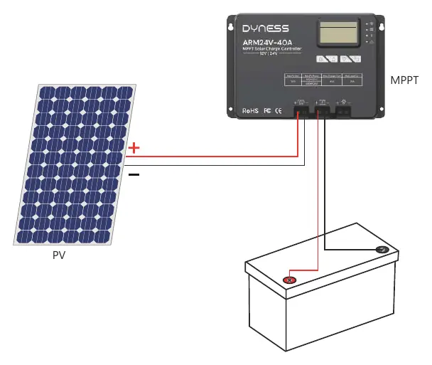
- Solar Panel and Controller: Recommended solar panel power is ≥400W. Use 12V (14.6V) LiFePO4 mode on your controller.
- Battery Charger: Use a 14.6V LiFePO4 charger. Avoid using alligator clips as they may cause terminal damage.
- Alternator/Generator: Ensure the generator supports AC output and use a suitable battery charger between the generator and the battery. Recommended charging voltage is 14.2V to 14.6V.
Series and Parallel Connections
You can connect up to 16 identical batteries (same capacity, BMS, brand, and purchased within 6 months). Before connecting, you must balance the voltage:
- Fully charge batteries separately (voltage at rest ≥13.35V).
- Connect all batteries in parallel and leave them together for 12-24 hours.
Connection Configurations:
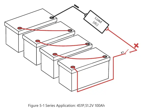
- Series: Increases system voltage (e.g., 4 in series = 51.2V).
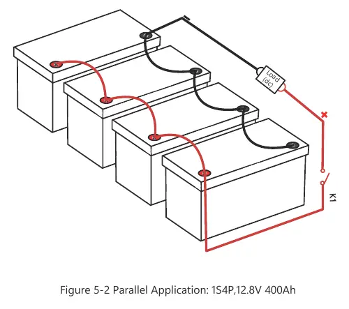
- Parallel: Increases system capacity (e.g., 4 in parallel = 400Ah).
- Series-Parallel: Combine both methods for increased voltage and capacity.
Troubleshooting and Activation
If the battery does not work or cannot be charged (Voltage <9V), the BMS may have shut it off for protection. Try these activation methods:
- Method 1: Disconnect all connections and leave the battery aside for 30 minutes. It should recover to >10V.
- Method 2: Use a 0V charger to charge the battery until the voltage is between 14V and 14.6V.
- Method 3: Connect an 18V-36V solar panel (no controller required) for 3-10 seconds.
Safety Precautions
- Do not reverse positive and negative poles.
- Do not use unofficial parts.
- Stop using immediately if the battery smells, changes color, leaks, or is deformed.
- Do not immerse in water or expose to fire/heat sources.
- Use high-stranded copper connectors and heavy gauge cables.
For warranty registration, contact [email protected].
Practical help
Common problems
Battery won't work or charge (Voltage <9V)
The BMS may have shut it off for protection. Try activating by disconnecting for 30 minutes, using a 0V charger, or connecting to an 18V-36V solar panel for 3-10 seconds.
Loose battery terminals
Tighten post bolts to 10-12 N·M to prevent heat buildup and terminal damage.
Before use
- Verify the product is working properly after unpacking.
- Ensure battery terminals are tightened to 10-12 N·M.
- Check that the battery is at 50% charge if storing for a long time.
- Use a professional LiFePO4 charger (14.6V).
- Wear insulating gloves before connecting.
Specs in practice
- Nominal Voltage
- 12.8V
- Rated Capacity
- 100Ah
- Max. Continuous Discharge Current
- 100A
- Protection Class
- IP65 (Dust tight and protected against water jets)
Images and diagrams
- Figure 3-1: MPPT Solar Controller connection diagram.
- Figure 5-1: Series connection diagram for 51.2V system.
- Figure 5-2: Parallel connection diagram for 400Ah system.
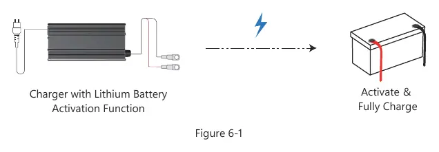
- Figure 6-1: Activation method using a charger.
Model compatibility
- Do not use as a starting battery.
- Only connect identical batteries (same capacity, BMS, brand, purchased within 6 months).
- Use high-stranded copper connectors and heavy gauge cables.

Manual page author
Emily Carter
User documentation editor
Prepares concise manual descriptions and highlights the most useful setup, operation, and maintenance information for readers.