Power / Energy Storage Systems
User Manual for Dyness POWERBOX Pro Energy Storage System
Quick guide for the Dyness POWERBOX Pro energy storage system. Includes installation steps, electrical connection, DIP switch configuration, LED status indicators, and troubleshooting.
Table of contents
Manual images
Click an image to enlargeQuick guide from the manual
The Dyness POWERBOX Pro is a lithium iron phosphate battery module designed for home energy storage. This guide covers essential installation, configuration, and maintenance procedures. Always ensure the system is installed by qualified professionals and complies with local safety regulations.
Safety Precautions
- Do not expose the battery to water or fire.
- Ensure the system is properly grounded before use.
- Do not mix batteries from different manufacturers, types, or ages.
- For long-term storage, recharge the battery every 6 months to over 80% capacity.
- If the battery is fully discharged, recharge it within 18 hours.
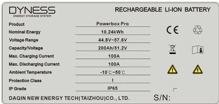
Product Specification
The POWERBOX Pro features a nominal energy of 10.24kWh, a nominal voltage of 51.2V, and a capacity of 200Ah. It is rated IP65 for dust and water resistance.
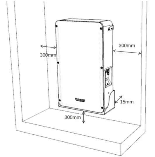
Equipment installation
The battery can be installed on the floor or mounted on a wall. Ensure the wall is solid brick or cement with a thickness of at least 100mm. Maintain a clearance of 300mm around the unit for ventilation.
Floor and Wall Mounting
- Use the provided positioning cardboard to mark screw hole positions.
- Drill 10mm diameter holes to a depth of at least 70mm.
- Secure the support brackets and battery bottom bracket using M6 expansion bolts.
- Mount the battery box onto the brackets and secure it with M6 bolts, applying a torque of 6NM.
Electrical installation
Before connecting, use a multimeter to verify cable continuity and polarity. Ensure the maximum discharge current of the load is within the battery's capacity.
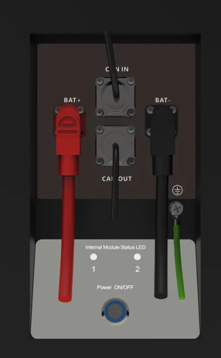
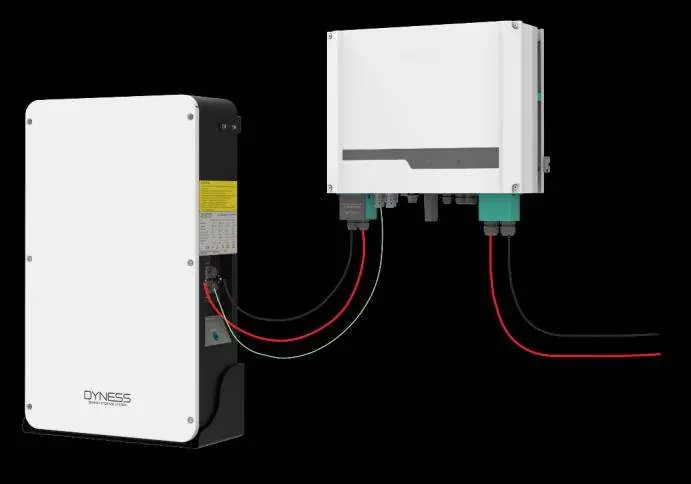
- Grounding: Connect the battery shell to the ground using a cable with a cross-sectional area of at least 6mm².
- Inverter Connection: Connect the positive and negative power cables to the inverter. Use the dedicated communication cable to connect the battery's CAN IN port to the inverter's communication interface.
- Parallel Connection: Up to 5 units can be connected in parallel. Use the appropriate power cables and communication cables as specified in the manual.
Battery module DIP switch definition and description
The DIP switch on the master module must be configured according to the connected inverter model. The factory default is usually Mode 1 (ADD: 0010). To change settings, you must contact Dyness to authorize opening the front panel. Once the master DIP is set, all slave modules should remain at ADD: 0000.
Battery system usage
To start the system, ensure the DC breaker is in the OFF state. Press the power button (Reset switch) to turn on the battery. The LED indicators will perform a self-check and turn green if the system is normal.
Troubleshooting
If the system encounters an issue, refer to the LED status indicators on the front panel:
- Red light flashing: Indicates protection mode (e.g., over-current, over-discharge, temperature abnormality).
- Yellow light on: Indicates a low voltage alarm; start charging immediately.
- Yellow light flashing (Master LED1): Indicates a communication fault between modules or with the inverter.
If you need technical help, contact the dealer or visit the official website at www.dyness-tech.com.cn.
Official resources from the manual
Practical help
Common problems
Indicator does not respond after power on
Ensure the power switch (Reset switch) is pressed and held for 3 seconds.
No DC output
Check if the DC circuit breaker on the side of the cabinet is turned on.
No DC output and red light is ON, buzzer beeping
Battery voltage is too low; charge the battery system.
Master POWERBOX Pro LED1 is yellow flashing
Check the external communication cable first, then check the internal communication cable.
LED 1 and 2 alternate flashing
Check external communication cable connection and verify slave module DIP settings.
Before use
- Ensure the battery is in a shutdown state before installation.
- Verify the wall or floor has sufficient load-bearing capacity.
- Confirm inverter compatibility and parameters.
- Check cable continuity and polarity with a multimeter.
- Ensure proper grounding with at least a 6mm² cable.
- Verify the DC breaker is in the OFF position.
Specs in practice
- Nominal Energy
- 10.24kWh
- Nominal Voltage
- 51.2V
- Max Charging/Discharging Current
- 100A
Images and diagrams
- Front Interface: Shows positive/negative sockets, COM ports, and LED indicators.
- DIP Switch: Used to define communication protocols and master/slave status.
- Parallel Connection: Diagram showing multiple units connected to a distribution box and inverter.
Model compatibility
- Supports parallel connection of up to 5 units.
- Requires specific DIP switch settings for different inverter brands (e.g., Goodwe, Solis, Victron, SMA, Growatt).

Manual page author
Emily Carter
User documentation editor
Prepares concise manual descriptions and highlights the most useful setup, operation, and maintenance information for readers.