Lighting / LED Drivers
User Manual for V-TAC 48100E ESS Series LFP Battery Pack
Quick guide for the V-TAC 48100E ESS Series LFP Battery Pack. Includes installation steps, wiring diagrams, parameter settings, maintenance, and troubleshooting.
Table of contents
Manual images
Click an image to enlargeQuick guide from the manual
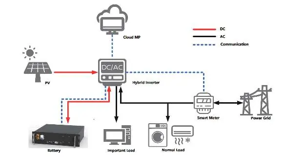
The V-TAC 48100E ESS Series LFP Battery Pack is designed for residential energy storage, back-up power, and PV self-consumption optimization. This manual provides essential instructions for installation, operation, and maintenance. Important: Do not connect battery packs in series. Ensure all installation work is performed by trained personnel using insulated tools.
Product Description
The battery pack utilizes lithium iron phosphate (LFP) technology, offering high energy density, long cycle life, and maintenance-free operation. It features a high-performance Battery Management System (BMS) for monitoring, alarm management, and communication via RS485/CAN protocols.
Installation
Before installation, ensure the battery is in the 'off' status. Use insulated tools to prevent electric shock. The battery must be installed in a cabinet or rack and secured with M6 bolts. Grounding is mandatory; connect the grounding wire from the battery to the cabinet ground point.
Cable Connection
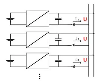
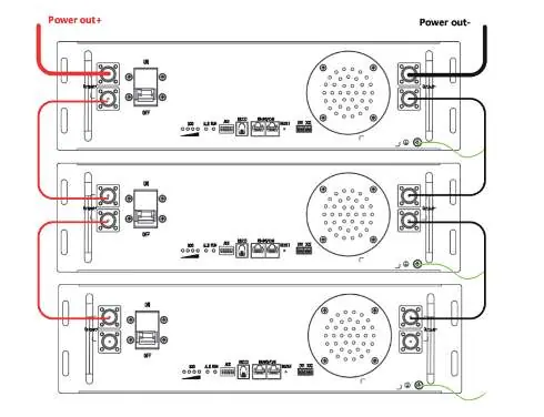
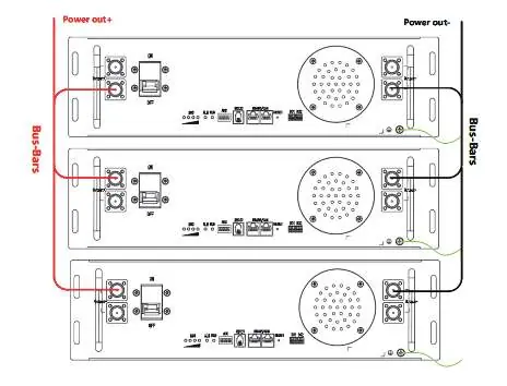
Connect the negative power cable to the negative bus bar and the battery negative terminal. Connect the positive power cable to the positive bus bar and the battery positive terminal. If the total current exceeds 100A, use bus-bars for parallel connections. Communication cables should be connected in a daisy-chain configuration using the RS485/CAN ports.
Power On
1. Power on the charger at the user terminal.2. Set the lithium battery MCB/Switch to ON.3. Observe the Run/Alarm indicators. If the RUN indicator is on and the ALARM indicator is off, the battery is operating normally.
Maintenance and Storage
Perform visual inspections every three months to check for terminal damage, leakage, or deformation. If the battery is not used for a long time, charge it to 40%-50% SOC. Storage temperature should be between 15°C and 35°C. Avoid storage in low-battery states (SOC ≤ 5%) to prevent permanent damage.
Troubleshooting
If the indicator does not flash, check the power cable connection, ensure the power switch is on, or charge the battery if it is in sleep mode. If communication fails, check the communication cable and ensure the BMS is not in sleep status. For inaccurate voltage displays, the voltage sampling line may be damaged.
Practical help
Common problems
Indicator does not flash
Check if the power cable is properly connected, ensure the power switch is on, or charge the battery if it is in sleep mode.
Unable to discharge
Check for damaged terminals, verify BMS communication, or ensure the power switch is turned on.
Communication fail
Check if the power switch is on, charge the battery if in sleep mode, or replace the damaged communication/network cable.
Inaccurate voltage display
The voltage sampling line may be damaged; replace the sampling cable or the BMS.
Before use
- Check the quantity of battery and accessories against the delivery list.
- Inspect the battery appearance for damage or leakage.
- Ensure all tools used for installation are insulated.
- Verify the battery is in 'off' status before starting installation.
- Confirm consistency of SOC and voltage between battery packs before parallel connection.
Specs in practice
- Nominal Voltage
- 48V for 15S configuration, 51.2V for 16S configuration.
- Nominal Capacity
- 100Ah.
- Charging Temp
- 0°C to 60°C (Recommended: 15°C to 35°C).
- Discharging Temp
- -20°C to 60°C (Recommended: 15°C to 35°C).
Images and diagrams
- Figure 3-1: System overview showing PV, Inverter, Battery, and Grid connection.
- Figure 6-3: Power cable connection to bus-bars.
- Figure 6-5: RS485/CAN communication cable daisy-chaining.
Model compatibility
- Do not connect battery packs in series.
- Parallel connection supports up to 6 groups without a control unit, or 15 groups with a control unit.
- The battery is not suitable for use in A/B environments (near ocean/pollution) without a high-protection air-conditioning cabinet (IP55 or higher).

Manual page author
David Miller
Documentation analyst
Organizes user manual content into clear summaries, with attention to model details, product context, and everyday usability.