Power / EV Chargers
Installation Guide for Easee Home and Easee Charge EV Chargers
Comprehensive installation and setup guide for Easee Home and Easee Charge electric vehicle chargers. Includes wiring diagrams, technical specifications, LED status indicators, and safety instructions.
Quick answers from the manual
Quick answer
- The Easee Home and Easee Charge are smart EV chargers that require installation by an authorized electrician. The process involves mounting the backplate, wiring the power supply, configuring the unit via the Easee Installer App, and attaching the Chargeberry module. p. 2, 8, 9, 10
Key actions
- Opening the charger p. 8
- Mounting the backplate p. 9
- Wiring the terminals p. 10
- Attaching the Chargeberry p. 12
First start
- Download the Easee Installer App and create an account. p. 11
- Configure the site in the app. p. 11
Show 4 more answers Show less
Problems and fixes
Red flashing light with warning sounds
Critical error. Turn off power, remove cable, and contact customer support.
p. 15
Red constant light
General error. Unplug and replug the charging cable.
p. 15Maintenance and reset
- The RCD is automatically tested every 24 hours or between charging sessions. p. 7
Technical specifications
| Parameter | Value | Meaning | Pages |
|---|---|---|---|
| Charging power | 1.4–22 kW | Adjustable based on available capacity. | p. 4 |
| Voltage | 3x 230/400V AC | Operating voltage range. | p. 4 |
| Terminal torque | 5 Nm | Required torque for wiring. | p. 5 |
| Degree of protection | IP54 | Water and dust resistance. | p. 5 |
Where to find it in the PDF
- Introduction p. 2
- Product overview p. 3
- Technical specifications p. 4, 5
- Installation instructions p. 8, 9, 10, 11
- Charging Robot interface p. 15, 16
Table of contents
Manual images
Click an image to enlargeQuick Guide from the Manual
This document provides installation instructions for the Easee Home and Easee Charge electric vehicle chargers. Installation must be performed by an authorized electrician in accordance with local, regional, and national regulations. The product requires a mobile device with an internet connection for setup.
Product Overview
The system consists of three main components:
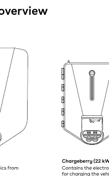
- Front cover: Protects the electronics from external influences.
- Chargeberry: Contains the electronics for charging the vehicle.
- Backplate: Used for attaching and connecting to the charging infrastructure.
Technical Specifications
Key parameters for the Easee Home and Easee Charge:
- Charging power: 1.4–22 kW (automatically adjusted).
- Voltage: 3x 230/400V AC (±10%).
- Connection: Type 2 socket (IEC 62196-2).
- Operating temperature: -30 °C to +40 °C.
- Protection: IP54 (backplate is IP22 without cover), IK10 impact resistance.
- Terminal torque: 5 Nm.
- Wire cross-section: 2.5 to 16 mm² (single conductors) or 2.5 to 10 mm² (parallel conductors).
Installation Steps
Follow these steps to install the charger:
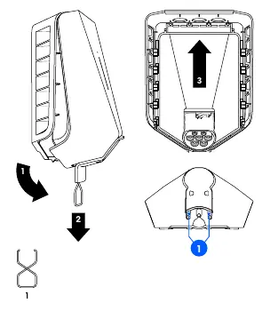
- Opening: Bend the lower rubber cover, insert the tool into the openings, pull to remove the front cover, and push the Chargeberry upwards to disconnect.
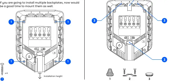
- Mounting: Fix the backplate to a solid wall using the 4 provided screws. Ensure the installation height is 130–140 cm (80–95 cm for accessibility).
- Preparing: Shorten the sealing plug to fit the cable, insert the cable through the entry, and secure it with the strain relief. Close unused entries with blind plugs.
- Wiring: Strip 12 mm of insulation from wires. Connect according to the grid type (TN/TT/IT). Tighten terminals to 5 Nm.
- Installing: Download the Easee Installer App, create an account, and follow the on-screen instructions to set up the site.
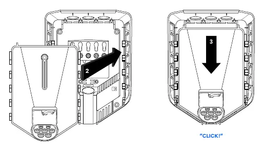
- Attaching: Position the Chargeberry in the backplate slots and press down until you hear a click.
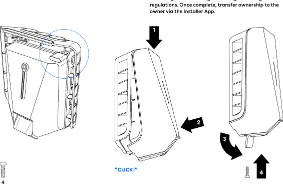
- Closing: Hang the front cover, press until it clicks, and secure with the locking screw at the bottom.
Residual Current Device (RCD)
The charger features an integrated RCD that breaks the current if residual current exceeds 6mA DC or 30mA AC. It is automatically tested every 24 hours or between charging sessions. An external RCD may be required depending on the installation type (e.g., if using Class I components or connecting other electrical equipment to the same circuit).
Charging Robot Interface
The light strip indicates the charger status:
- White (constant): Standby or car connected.
- White (pulsating): Charging in progress.
- Blue (constant/pulsating): Smart charging enabled/in progress.
- Red (flashing): Critical error; requires power cycle or replacement.
- Red (constant): General error; unplug and replug the cable.
- Yellow (flashing): Waiting to be configured.
Manufacturer information
Easee
Practical help
Common problems
Red flashing light with warning sounds
Critical error. Turn off power, remove charging cable, and contact customer support. The unit may need replacement.
Red constant light
General error. Unplug the charging cable and replug it. If the light persists, check the Easee App or knowledge base.
Yellow flashing light
The charger is waiting to be configured. Consult an authorized electrician.
Wires connected incorrectly
Indicated by red constant light with warning sounds. Consult an authorized electrician.
Before use
- Ensure power is turned off before starting installation.
- Verify the installation wall has sufficient load-bearing capacity.
- Ensure the installation height is 130–140 cm.
- Use an authorized electrician for all electrical work.
- Ensure the mobile device has an internet connection for the Installer App.
- Check that the PE wire cross-section is equal to or larger than the phase wire.
Show more Show less
Specs in practice
- Type 2 socket
- Standard connection point for electric vehicle charging cables.
Images and diagrams
- Opening: Use the tool to release the front cover and disconnect the Chargeberry.
- Mounting: Use 4 screws to fix the backplate to the wall.
- Wiring: Connect wires to terminals according to the grid type (TN, IT, or TT).
- Attaching: Press the Chargeberry into the backplate until it clicks.
- Closing: Secure the front cover with the locking screw.
Model compatibility
- Compatible with TN, IT, and TT networks.
- Load balancing supported for up to 3 units (Easee Home) or 101 units (Easee Charge) per circuit.
- Requires mobile device with Bluetooth or NFC for installation.

Manual page author
Michael Turner
Technical manual editor