Furniture / Storage Cabinets
Installation Guide for Ebern Designs Essman Steel 2-Tier Locker
Step-by-step assembly instructions for the Ebern Designs Essman Steel 2-Tier Locker. Includes a complete parts list, hardware requirements, and detailed installation steps for all 6 assembly stages.
Table of contents
Manual images
Click an image to enlargeQuick guide from the manual
Before beginning the assembly of your Ebern Designs locker, ensure you have a flat surface to work on. Verify that all parts are present and undamaged according to the parts list provided in the manual. Wear the included gloves during assembly for safety.
Parts and accessories
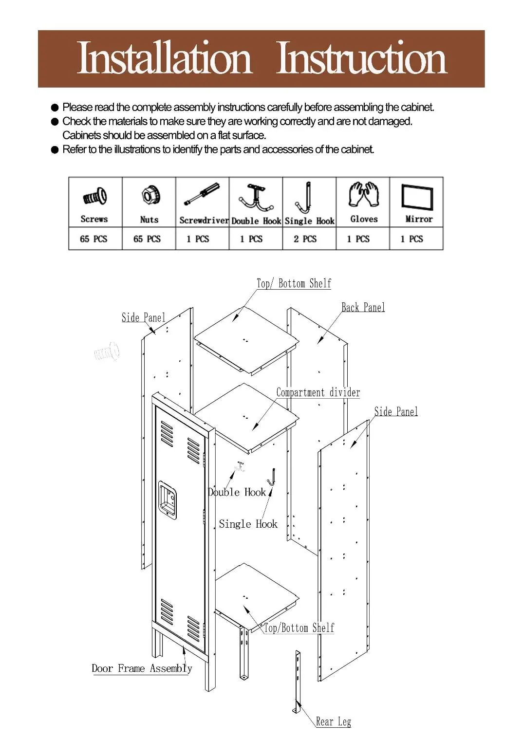
- Screws: 65 pcs
- Nuts: 65 pcs
- Screwdriver: 1 pc
- Double Hook: 1 pc
- Single Hook: 2 pcs
- Gloves: 1 pair
- Mirror: 1 pc
Assembly instructions
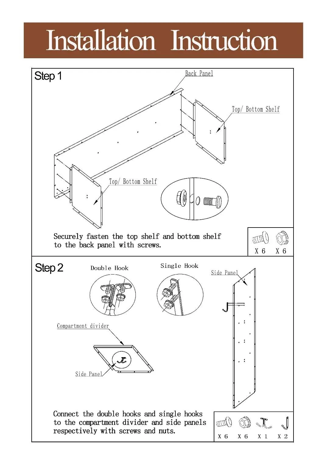
Step 1: Back panel and shelves
Securely fasten the top shelf and bottom shelf to the back panel using the provided screws.
Step 2: Hooks and panels
Connect the double hooks and single hooks to the compartment divider and side panels using the screws and nuts.
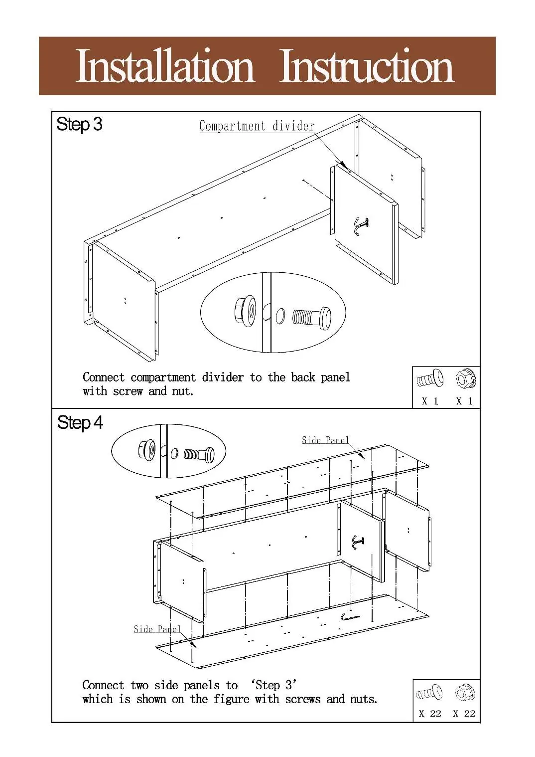
Step 3: Compartment divider
Connect the compartment divider to the back panel using screws and nuts.
Step 4: Side panels
Connect the two side panels to the assembly created in Step 3 using screws and nuts.
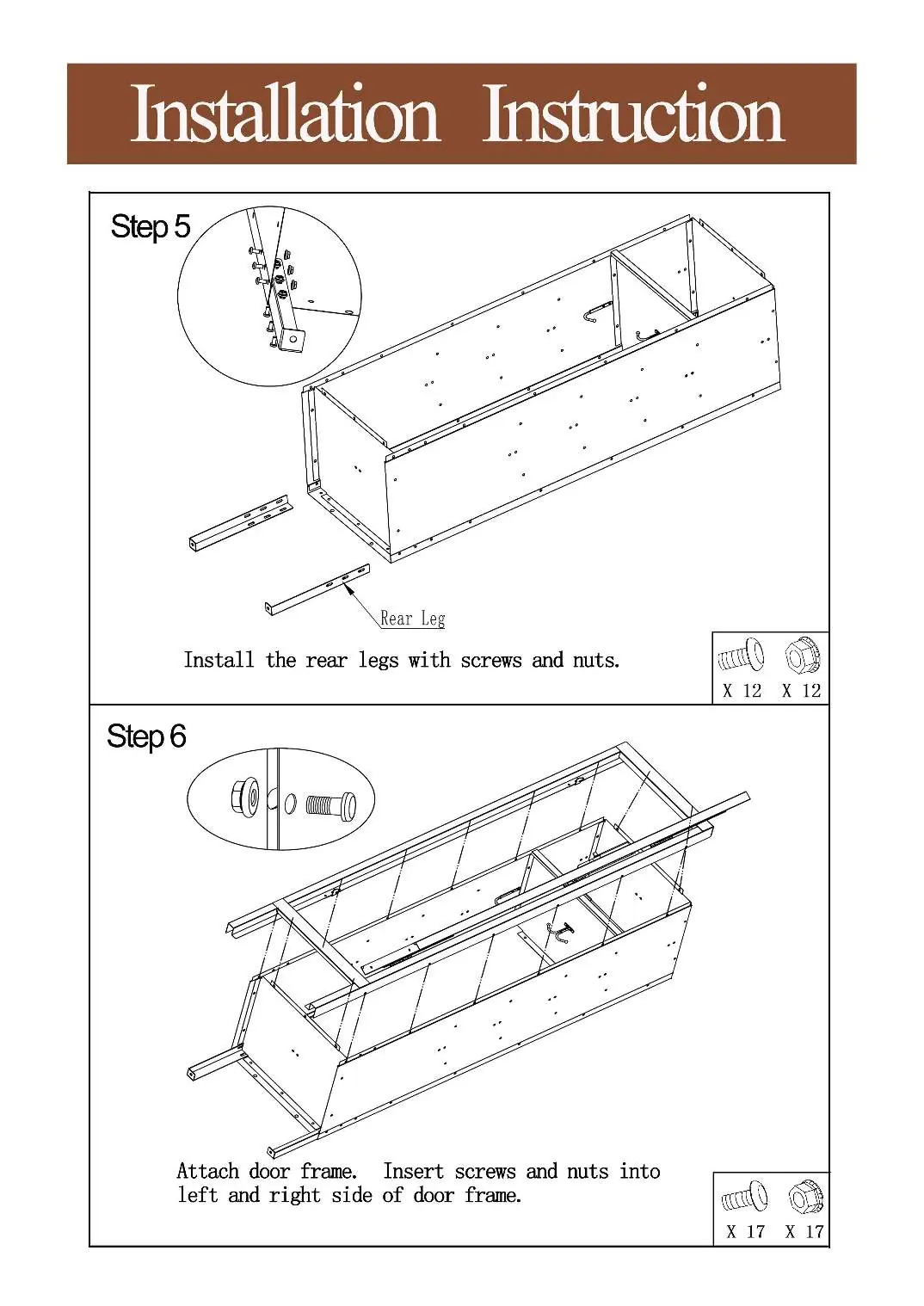
Step 5: Rear legs
Install the rear legs to the base of the unit using screws and nuts.
Step 6: Door frame
Attach the door frame to the main assembly by inserting screws and nuts into the left and right sides of the door frame.
Practical help
Common problems
Parts missing or damaged
Check all materials against the parts list before starting assembly to ensure they are working correctly and are not damaged.
Before use
- Ensure assembly area is a flat surface
- Verify all 65 screws and 65 nuts are present
- Wear provided gloves for safety
- Identify all panels and hooks before starting
Show more Show less
Images and diagrams
- The manual provides exploded view diagrams for each step showing the exact placement of screws and nuts for every panel and hook.

Manual page author
David Miller
Documentation analyst