Hvac / Air Conditioners
EcoFlow PowerKit 10kWh System User Guide
Comprehensive setup and installation guide for the EcoFlow PowerKit 10kWh system, covering mounting, component connection, and app integration.
Table of contents
Manual images
Jump to the sectionSystem Overview
The EcoFlow PowerKit 10kWh is a versatile energy management solution designed for various applications, including recreational vehicles, off-grid builds, and home backup systems. The core of the system is the Power Hub, which acts as the central control unit for managing energy flow between solar panels, batteries, the grid, and your appliances. The system is modular, allowing for flexible configurations based on your specific power needs.
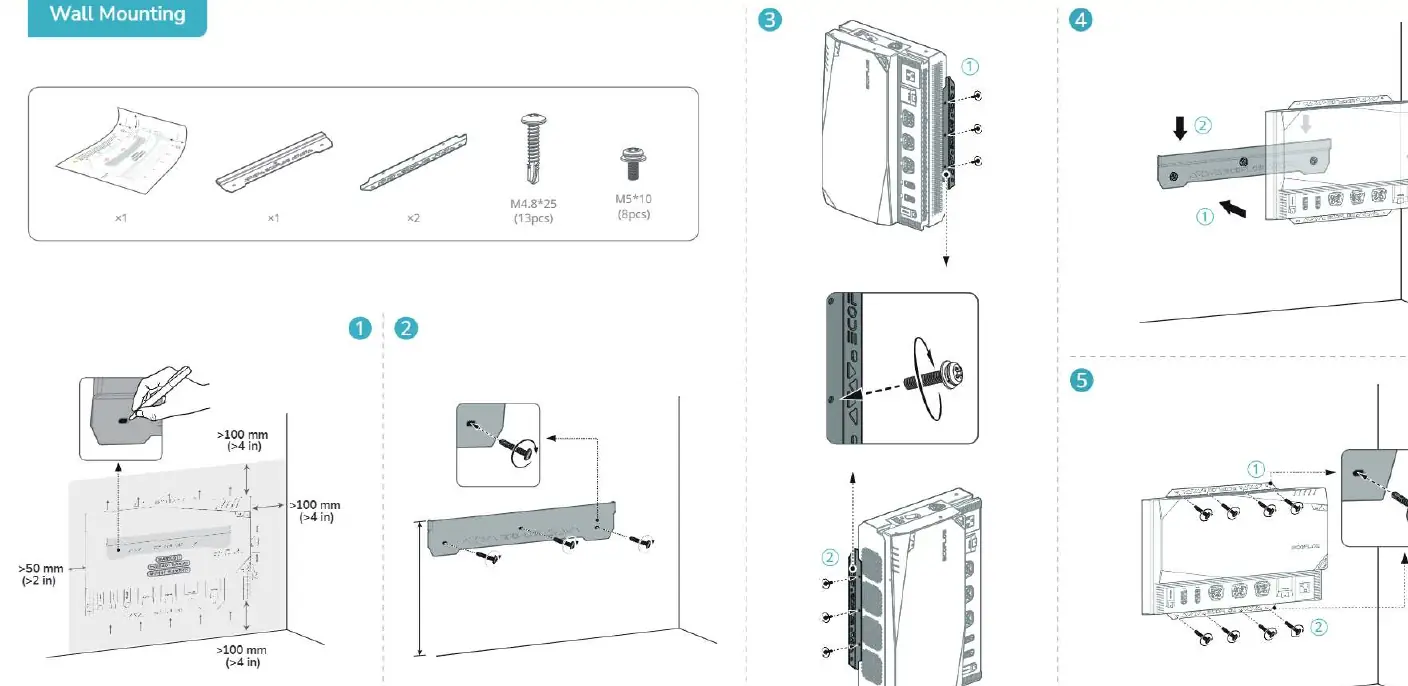
Installation and Mounting
Proper installation is critical for the safety and performance of your PowerKit. The Power Hub requires adequate ventilation to prevent overheating. Ensure there is at least 100mm of clearance around the unit. The system supports both wall mounting and recessed installation for the AC/DC Smart Distribution Panel. When mounting the Power Hub, use the provided brackets and screws to secure it firmly to a stable surface. Always follow the orientation guidelines provided in the diagrams to ensure optimal airflow and cable management.
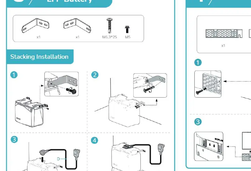
Battery Stacking and Connection
The 2kWh and 5kWh LFP batteries are designed for easy stacking. When installing multiple batteries, ensure they are placed on a level surface and secured using the provided mounting hardware. Connect the batteries to the Power Hub using the designated cables. It is essential to follow the connection sequence outlined in the manual to avoid electrical faults. Ensure all cable connections are tight and properly seated in their respective ports.
Connecting Components
The system utilizes various cables for different inputs and outputs. The AC/DC Smart Distribution Panel connects to your home or vehicle circuits, while the Power Hub manages inputs from solar panels (PV IN), the alternator (ALT IN), and shore power (AC IN). Always verify the polarity and connection type before plugging in any cables. The system also includes a Power Kit Console for monitoring and control, which connects directly to the Power Hub.
App Integration and Maintenance
To maximize the utility of your PowerKit, connect it to the EcoFlow App. This allows for real-time monitoring, system updates, and remote control of your power settings. The app requires a 2.4GHz Wi-Fi connection for internet setup. Regular maintenance involves checking all cable connections for signs of wear or looseness and ensuring that ventilation paths remain clear of dust and debris. If you encounter system malfunctions, check the app for error codes and ensure all communication cables, such as the RJ45 CAN bus terminator, are correctly installed.
Manufacturer information
EcoFlow
Practical help
Common problems
System malfunction
Ensure all communication cables and the RJ45 CAN bus terminator are correctly connected.
Overheating
Ensure at least 100mm of clearance around the Power Hub for proper ventilation.
App connection issues
Ensure you are using a 2.4GHz Wi-Fi network and that Bluetooth is enabled on your mobile device.
Before use
- Verify all mounting hardware is securely fastened.
- Ensure ventilation paths are clear of obstructions.
- Check that all cable connections are tight and correctly oriented.
- Confirm the battery stacking is stable and level.
- Verify the RJ45 CAN bus terminator is installed.
- Ensure the system is connected to a stable power source or solar array.
Specs in practice
- RJ45 CAN bus
- Communication port for system data and component synchronization.
Images and diagrams
- The Power Hub acts as the central brain connecting all energy sources and loads.
- Battery stacking diagrams show the correct orientation for vertical expansion.
- The AC/DC distribution panel layout indicates where to connect household circuits.
- Wiring diagrams illustrate the difference between RV, off-grid, and home backup setups.
Model compatibility
- The system supports 2.4GHz Wi-Fi for internet connectivity.
- The Power Kit Console and Smart Distribution Panel must be connected to the Power Hub via the CAN bus.

Manual page author
David Miller
Documentation analyst
Organizes user manual content into clear summaries, with attention to model details, product context, and everyday usability.