Power / Solar Accessories
Installation Instructions for EG4 18KPV External RSD Initiator
Quick installation guide for the EG4 18KPV External Rapid Shutdown Initiator. Includes wiring steps, safety warnings, and instructions for integrating with Tigo Cloud Connect Advanced.
Quick answers from the manual
Quick answer
- To install an external RSD initiator, you must cut the yellow wire on the 18KPV interface board, connect it to a connector, and wire it to the Normally Closed (NC) switch of your RSD initiator. For Tigo CCA integration, connect the CCA to the 12V ports on the interface board and the Aux port to the Normally Open (NO) switch. p. 4, 5, 6, 8
Key actions
- Cut and strip the yellow wire on the interface board. p. 5
- Connect the RSD initiator switch to the female connector. p. 6
Problems and fixes
System in constant RSD state
Install a jumper on the female connector if the switch is removed.
p. 7Technical specifications
| Parameter | Value | Meaning | Pages |
|---|---|---|---|
| CCA Power | 24V @ 1A | Power provided to Tigo Cloud Connect Advanced from interface board. | p. 8 |
Where to find it in the PDF
- Safety Instructions p. 2, 3
- RSD Initiator Installation p. 4, 5, 6, 7
- Tigo CCA Integration p. 8, 9
Table of contents
Manual images
Click an image to enlargeQuick guide from the manual
This document provides instructions for installing an external Rapid Shutdown (RSD) initiator switch on the EG4 18KPV inverter. It also covers the integration of the Tigo Cloud Connect Advanced (CCA) system. All work must be performed by qualified personnel.
Safety instructions
Before beginning any work, read all safety instructions. Incorrect installation may cause injury, death, or equipment damage.
- High Voltage Warning: Always use a voltmeter to confirm no voltage is present before working on the inverter.
- Disconnects: Ensure external DC disconnects, AC switches, and battery breakers are in the open or off position.
- Operation: Do not open the inverter while it is operating. Do not make connections or disconnections while the system is live.
- PPE: Installers must use professional insulative equipment.
- Temperature: The inverter and system parts can be hot during operation; avoid touching surfaces other than the LCD and buttons.
Installing an external Rapid Shutdown initiator
Parts needed: Connector set, RSD Initiator (with one Normally Closed and one Normally Open switch), and 16AWG or larger wire.
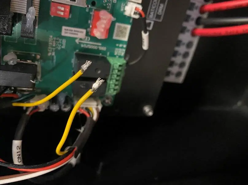
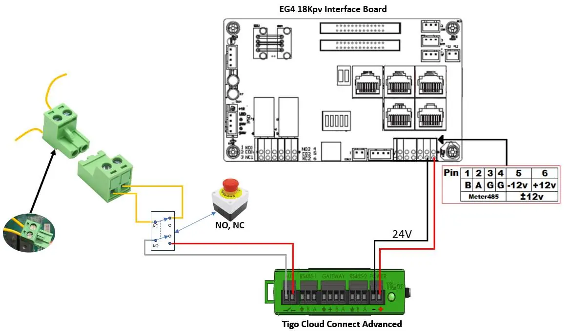
- Locate the wiring harness on the left side of the interface board containing the Yellow, Red, Brown, and White wires.
- Carefully cut and strip both ends of the yellow wire.
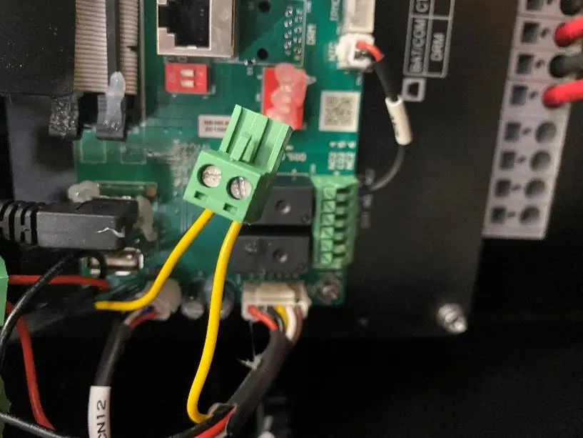
- Fasten both ends of the yellow wire to the provided connector.
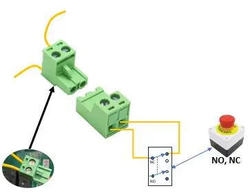
- Connect the Normally Closed (NC) switch of the RSD Initiator to the female connector.
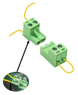
Warning: If the switch is removed or disconnected, the system will enter a constant RSD state and the PV will not power up. If operating without the button, a jumper must be installed on the female connector.
RSD Initiator function
When the RSD initiator is pressed, the transmitter inside the EG4 18KPV stops broadcasting the SunSpec keep-alive signal. RSD receivers at the solar panels detect this absence, open the PV circuits, and de-energize the system. The inverter also de-energizes the AC output.
Rapid Shutdown control of a Tigo Cloud Connect Advanced
To prevent the 'Dark Start' issue where the CCA shuts down due to low battery, the 18KPV can power and control the CCA.
- Install the external RSD Initiator as described above.
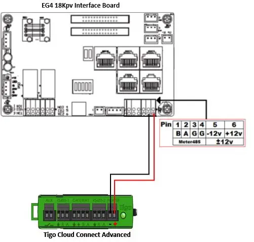
- Connect the CCA to the '+12V' and '-12V' ports on the 18KPV interface board (provides 24V @ 1A).
- Connect the CCA Aux port to the Normally Open (NO) switch in the External Rapid Shutdown Initiator.
Manufacturer information
EG4 Electronics LLC
Practical help
Common problems
System in constant RSD state
If the switch is removed or disconnected, install a jumper on the female connector to restore operation.
Dark Start issue with Tigo CCA
Power the CCA from the 18KPV interface board (+12V/-12V ports) instead of the inverter AC output.
Before use
- Ensure all work is performed by qualified personnel.
- Verify all DC, AC, and battery breakers are in the 'off' or 'open' position.
- Use a voltmeter to confirm no voltage is present before starting installation.
- Inspect existing wiring to ensure it meets specifications.
- Ensure all warning labels are visible.
Specs in practice
- CCA Power Output
- The 18KPV interface board provides 24V @ 1A to the Tigo CCA.
Images and diagrams
- The wiring harness on the interface board contains the yellow wire that must be cut and connected to the RSD switch.
- The Tigo CCA requires connection to the +12V and -12V pins on the interface board for power.
- The CCA Aux port connects to the Normally Open (NO) switch of the RSD initiator.
Model compatibility
- Requires SunSpec compliant RSD Receivers.
- Integrated RSD initiator will not trigger an RSD sequence on the Tigo Cloud Connect Advanced; an external initiator is required for combined control.

Manual page author
Michael Turner
Technical manual editor
Reviews PDF manuals for structure, safety notes, and practical product details so readers can find the right information quickly.