Power / Batteries & Chargers
Quick-Start Guide for EG4 WallMount All Weather Battery
A comprehensive quick-start guide for the EG4 WallMount All Weather battery. This manual covers safety precautions, installation requirements, mounting procedures, wiring, parallel battery configurations, and BMS communication settings.
Table of contents
Manual images
Click an image to enlargeQuick Start Guide
This document provides essential instructions for the installation and setup of the EG4 WallMount All Weather battery. Always ensure all system components are up to date and follow local electrical codes.
Safety Precautions
Working with high-voltage battery systems carries risks. Follow these critical safety measures:
- High Voltage Warning: Always use a voltmeter to confirm there is no DC or AC voltage present before working on the battery.
- Disconnects: Ensure all external DC disconnect switches, AC breakers, and battery module breakers are in the "off" or "open" position before installation.
- PPE: Installers must use professional insulative equipment (PPE).
- Connections: Do not make or break any connections (PV, battery, grid, communication) while the battery is operating.
- Grounding: Ensure the battery is properly grounded according to NEC (ANSI/NFPA 70) standards.
Installation Requirements
The WallMount battery is heavy and requires careful handling.
- Lifting: Use a lift or team-lift technique. Remove temporary lifting handles before making connections.
- Clearance: Maintain at least 12 inches of clearance on all sides of the unit for airflow.
- Mounting Height: If wall-mounting, ensure a minimum clearance of 28.0625 inches from the ground.
- Environment: Install in a location that prevents flooding. If installing on flat ground, ensure proper drainage.
Mounting the Battery
The battery can be installed standalone, with a conduit box, or integrated with an 18kPV inverter.
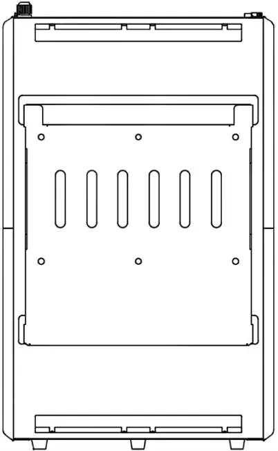
- Standalone: Remove the mounting bracket from the battery, secure it to the wall using a level and expansion bolts, hook the battery onto the bracket, and secure it with the 4 side screws.
- Conduit Box: Follow the same mounting procedure, then attach the optional conduit box to the top of the battery using the included hardware.
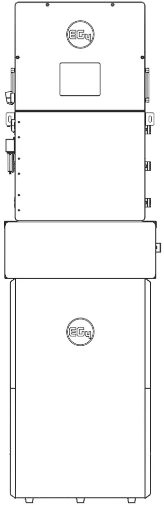
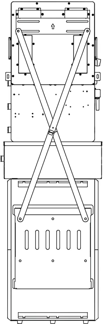
- 18kPV Integration: Use the provided X-bracket behind the mounting plate. Ensure the inverter's bottom knockouts align with the conduit box.
Wiring and Connections
Refer to the following guidelines for cable sizing and torque:
- 1/0 AWG (53.5 mm²): Max 10 ft. distance, 165 in-lbs (18.6 Nm) torque.
- 2/0 AWG (67.4 mm²): Max 20 ft. distance, 165 in-lbs (18.6 Nm) torque.
- 4/0 AWG (107 mm²): Max 10 ft. distance, 275 in-lbs (31.1 Nm) torque.
- 250 kcmil (127 mm²): Max 20 ft. distance, 275 in-lbs (31.1 Nm) torque.
Important: Ensure proper polarity before making connections. The battery is capable of 200A discharge; ensure the inverter is configured to handle this current.
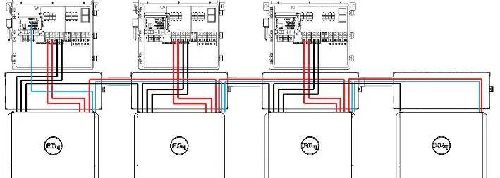
Parallel Installation
To install multiple batteries in parallel:

- Ensure all breakers are off and verify zero voltage with a multimeter.
- Set the DIP switch address on the master battery to 1. Set other batteries to ascending addresses.
- Reset the BMS via the power button to register the address change.
- Connect batteries using CAT 5, 5e, or 6 cables via the "Battery-Com" ports.
- Connect the master battery (ID 1) directly to the inverter BMS port.
BMS Communications
The battery interfaces with compatible inverters via RS485 or CAN bus protocol. To change the inverter protocol:
- Power off DC breakers and BMS.
- Set the master battery DIP switch to address 64 (all switches ON).
- Restart the BMS, hold the "Return" key for 5 seconds to enter the "Protocol Setting" menu.
- Select the appropriate CAN/RS485 protocol for your inverter.
- Reset the master DIP switch to address 1 and power cycle the BMS.
Firmware Updates
Ensure all system components are up to date. Visit the EG4 Electronics website to download the latest firmware for the WallMount All Weather battery.
Manufacturer information
EG4 Electronics LLC
Practical help
Common problems
Battery not communicating with inverter
Verify DIP switch settings (Master must be ID 1), ensure CAT 5/6 cable is connected, and confirm the correct protocol is selected in the BMS menu.
High voltage warning
Use a voltmeter to confirm no DC or AC voltage is present at disconnects before working on the battery.
Mounting clearance issues
Ensure at least 12 inches of clearance on all sides and a minimum of 28.0625 inches from the ground.
Before use
- Read all safety instructions.
- Ensure all circuit breakers are in the 'off' or 'open' position.
- Verify wire size and torque values.
- Use a voltmeter to confirm zero voltage.
- Ensure proper grounding to the M6 grounding screw.
- Remove temporary lifting handles.
Specs in practice
- 1/0 AWG (53.5 mm²)
- Wire size for 10 ft. max distance, 165 in-lbs torque.
- 2/0 AWG (67.4 mm²)
- Wire size for 20 ft. max distance, 165 in-lbs torque.
- 4/0 AWG (107 mm²)
- Wire size for 10 ft. max distance, 275 in-lbs torque.
- 250 kcmil (127 mm²)
- Wire size for 20 ft. max distance, 275 in-lbs torque.
Images and diagrams
- Parallel wiring diagram shows connections between multiple batteries and the inverter.
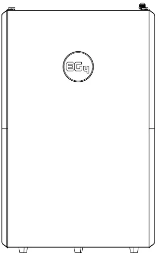
- Orientation examples show stacking configurations with 18kPV, 12kPV, and 6000XP inverters.
Model compatibility
- Compatible with EG4, Growatt, Sol-Ark, Deye, Megarevo, Victron, Luxpower, and SMA inverters.

Manual page author
Michael Turner
Technical manual editor
Reviews PDF manuals for structure, safety notes, and practical product details so readers can find the right information quickly.