Power / Solar Accessories
User Guide for EG4 18kPV Monitoring Adapter
Quick setup guide for the EG4 18kPV Monitoring Adapter. Learn how to register your account, connect the device via Ethernet, and interpret LED status indicators for troubleshooting.
Quick answers from the manual
Quick answer
- The EG4 18kPV Monitoring Adapter connects your inverter to the internet for monitoring. Setup requires registering an account via the EG4 Monitor app or website using a customer code, and connecting the device to your router using a 568B Ethernet cable. p. 1
Key actions
- Register an account p. 1
- Connect the Ethernet cable p. 1
First start
- Obtain a customer code from your installer or distributor to register your account. p. 1
Problems and fixes
INV LED flashing
Check the connection between the WLAN Dongle and the inverter; ensure connectors are fully inserted.
p. 2Technical specifications
| Parameter | Value | Meaning | Pages |
|---|---|---|---|
| Maximum Cable Length | 65 ft (20m) | Maximum communication distance between the inverter and WLAN dongle. | p. 2 |
Where to find it in the PDF
- Quick Setup Guide p. 1
- LED Indicators and Troubleshooting p. 2
Table of contents
Manual images
Click an image to enlargeQuick guide from the manual
The EG4 18kPV Monitoring Adapter allows you to monitor your inverter system. To get started, you must obtain a customer code from your installer or distributor, register an account via the EG4 Monitor app or website, and connect the adapter to your router using a 568B Ethernet cable.
Account registration
To create an end-user account, you can use one of the following methods:
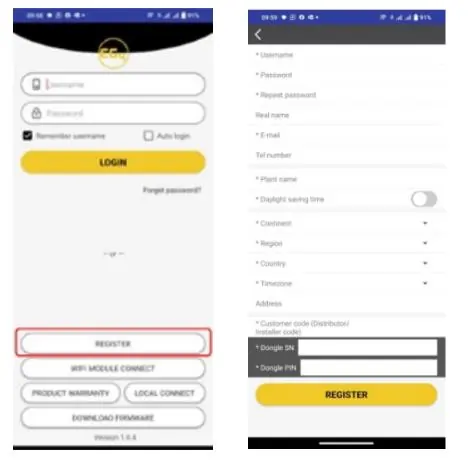
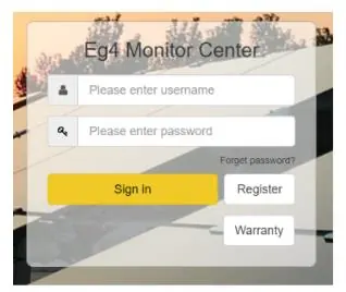
- Web registration: Visit https://monitor.eg4electronics.com/
- Mobile App: Download the 'EG4 Monitor' app from the Google Play Store or Apple App Store.
Note: A customer code is required for registration. This code must be provided by your installation personnel or distributor. If you need to create a distributor or installer account, contact [email protected].
Hardware installation
Follow these steps to connect the monitoring adapter:
- Prepare a common Ethernet cable with a 568B configuration.
- Connect one end of the cable to a port on your router.
- Connect the other end of the cable to the WLAN Dongle.
Important: It is recommended to use a shielded cable. The cable length should not exceed 65 ft (20m) between the inverter and the WLAN dongle.
LED indicators
The adapter features four LED indicators to show system status:
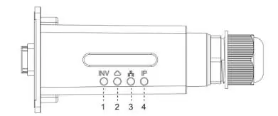
- INV LED (1): Indicates communication between the WLAN Dongle and the inverter.
- Cloud LED (2): Indicates communication between the WLAN Dongle and the internet.
- Network LED (3): Indicates communication between the WLAN Dongle and the router.
- IP LED (4): Indicates IP address status.
Troubleshooting
If you encounter issues, check the LED status:
- All LEDs are ON: Communication is normal.
- INV LED flashing: Failure of communication between the WLAN Dongle and the inverter. Check the connection and ensure connectors are fully inserted.
- Cloud LED flashing: Failure of connection to the internet. Check if the WLAN Dongle has been added to the power station.
- Network LED flashing: Failure of connection to the router. Ensure the router is connected to the internet, the cable length is under 65ft (20m), and a 568B configuration cable is used.
- IP LED flashing: The router has not enabled dynamic IP address allocation.
Official resources from the manual
Manufacturer information
EG4 Electronics LLC
Practical help
Common problems
INV LED continuously flashing
Check the connection between the WLAN Dongle and the inverter; ensure connectors are fully inserted.
Network LED continuously flashing
Verify the router is connected to the internet, ensure the cable length is under 65ft (20m), and confirm a 568B configuration cable is used.
IP LED continuously flashing
Ensure the router's automatic IP allocation feature is enabled.
Cloud LED continuously flashing
Check if the WLAN Dongle has been added to the power station.
Before use
- Obtain a customer code from your installer or distributor.
- Download the 'EG4 Monitor' app or visit the registration website.
- Prepare a 568B configuration Ethernet cable.
- Ensure the cable length is less than 65 ft (20m).
- Use a shielded Ethernet cable (recommended).
Specs in practice
- Max Cable Length
- 65 ft (20m) maximum distance between the inverter and the WLAN dongle.
Images and diagrams
- The LED indicator diagram shows four lights labeled INV, Cloud, Network, and IP, corresponding to different communication statuses.
- The connection diagram illustrates the Ethernet cable connecting the router to the WLAN dongle.
Model compatibility
- Requires a customer code for account registration.
- Compatible with 568B configuration Ethernet cables.

Manual page author
David Miller
Documentation analyst
Organizes user manual content into clear summaries, with attention to model details, product context, and everyday usability.