Industrial / Energy Monitoring
Installation Guide for GivEnergy All in One + Giv-Gateway
Professional installation guide for the GivEnergy All in One and Giv-Gateway system. Includes detailed mounting instructions, wiring diagrams for AC grid and communication, commissioning procedures, and safety requirements for approved...
Table of contents
Manual images
Click an image to enlargeImportant Information
The installation of the GivEnergy All in One and Giv-Gateway must be carried out by a GivEnergy Approved Installer in accordance with IEE Wiring Regulations. The system retains high voltage even when disconnected. Do not attempt to repair the equipment yourself.
System Overview
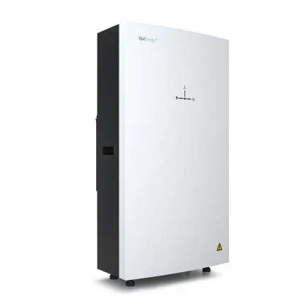
The All in One unit contains a bidirectional inverter and a 13.5kWh lithium iron phosphate battery. When paired with the Giv-Gateway, the system provides whole-home backup during power outages, allows for grid charging during off-peak times, and supports solar PV integration.
Unboxing and Components
Upon delivery, ensure all accessories are present and the unit is free from damage. The All in One box includes the unit, mounting brackets, expansion bolts, WiFi antenna, and a spirit level. The Giv-Gateway box includes the gateway, mounting bracket, screws, wall plugs, antenna, and key.
Installation Requirements
- Location: Must be easily accessible, well-ventilated, and not in direct sunlight or near water sources.
- Orientation: Must be installed vertically with connections at the bottom.
- Clearance: Maintain adequate clearance for heat dissipation (300mm top/sides for All in One; 200mm for Giv-Gateway).
- Mounting: Ensure the wall is sufficient to hold the weight of the units.
Step-by-Step Installation
All in One
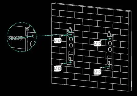
- Mark the position of the bracket holes horizontally on the wall and drill 3 holes at least 75mm deep.
- Fix the mounting bracket to the wall using expansion bolts.
- Mount the unit onto the bracket and adjust the supporting feet to ensure it is level.
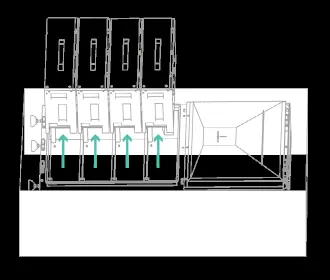
- Re-insert battery modules into the shelves and secure them.
- Replace the front cover and secure with screws.
Giv-Gateway
- Mark the position of the bracket holes and drill 2 holes at least 75mm deep.
- Fix the mounting bracket to the wall.
- Mount the Giv-Gateway onto the bracket and secure it.
Wiring and Connections
All in One: Use a minimum 6mm² cable for AC supply. Connect the communication wire to socket D in the wiring compartment. Ensure the RJ45 cable is not a cross-over cable.
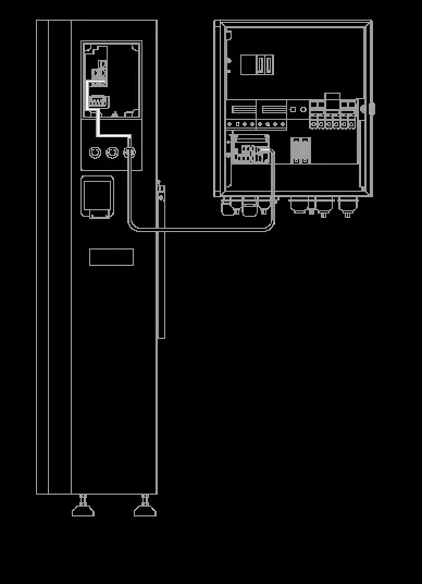
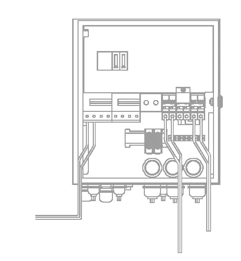
Giv-Gateway: Ensure the house is isolated from the main supply before installation. The gateway should be installed between the supply meter and the consumer unit. Use 16-25mm² tails for grid and load connections.
Commissioning
All systems must be commissioned to ensure correct battery and meter communications. Sign into the online portal at https://portal.givenergy.cloud with your GivEnergy Engineer login. Parameters must be set according to the specific battery system.
Work Modes
- Off Peak Charging: Prioritises charging during off-peak times when energy is cheaper.
- Solar Charging: Prioritises charging using excess solar generation.
- Back Up / Island Mode: Provides power to the whole home in the event of a grid failure.
- Off Grid Operation: Allows remote disconnection from the grid via the App or Portal.
Maintenance
The whole system must be powered down before cleaning or maintenance. Do not use cleaning products on the surface. Perform annual checks for visible damage, discolouration of switches, and cable integrity. Ensure the top of the unit remains unobstructed.
Official resources from the manual
Practical help
Common problems
System not operating correctly
Ensure the system has been commissioned via the online portal.
Inverter not starting
Check that battery voltage is higher than 270V DC or that the Giv-Gateway is providing AC voltage.
Communication failure
Verify that the RJ45 communication cable is not a cross-over cable and is terminated identically at both ends.
Before use
- Verify the wall can support the weight of the unit (173.7kg for All in One).
- Ensure the installation location is well-ventilated and accessible.
- Check that all accessories from the packaging list are present.
- Confirm grid power reading matches the meter screen.
- Ensure the system is isolated from the main supply before wiring.
Specs in practice
- Depth of Discharge
- 100% - The total capacity of the battery that can be utilized.
- Protection Class
- IP65 - The unit is dust-tight and protected against water jets.
- Noise Emission
- <30dB - The typical operating noise level of the unit.
Images and diagrams
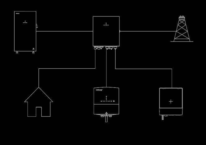
- System Diagram: Illustrates the connection flow between the Grid, Giv-Gateway, All in One, Load, EV charger, and PV inverter.
Model compatibility
- Up to 6 systems can be connected in parallel.
- Do not connect the inverter to a generator or other power source.

Manual page author
Emily Carter
User documentation editor
Prepares concise manual descriptions and highlights the most useful setup, operation, and maintenance information for readers.