Lighting / Fixtures
User Manual for Elk Home 89670/1 Caroline 1-Light Vanity Light
Installation and user guide for the Elk Home 89670/1 Caroline 1-Light Vanity Light. Includes detailed wiring instructions, mounting procedures, and bulb installation requirements.
Quick answers from the manual
Quick answer
- This manual provides instructions for installing the Elk Home 89670/1 vanity light, including mounting bracket installation, electrical wiring, and bulb/shade assembly. p. 1, 2
Key actions
- Install the mounting bracket to the junction box. p. 1
- Connect fixture wires to house supply wires. p. 1, 2
- Install the bulb and secure the glass shade. p. 2
First start
- Disconnect power at the main fuse box before beginning installation. p. 1
Show 2 more answers Show less
Technical specifications
| Parameter | Value | Meaning | Pages |
|---|---|---|---|
| Bulb Type | E12 candelabra | Recommended bulb type for the fixture | p. 2 |
| Wire Insulation Strip Length | 3/4 inch | Amount of insulation to remove from fixture wires | p. 1 |
Where to find it in the PDF
- English Installation Instructions p. 1, 2
- French Installation Instructions p. 3, 4
- Spanish Installation Instructions p. 5, 6
Table of contents
Manual images
Click an image to enlargeQuick guide from the manual
This document provides installation instructions for the Elk Home 89670/1 vanity light. Before beginning, ensure the power is disconnected at the main fuse box. The installation requires basic electrical knowledge; if you are unfamiliar with the National Electrical Code (NEC) or local codes, consult a certified electrician. Ensure all parts are present before starting assembly.
Safety and Preparation
Warning: Always disconnect power at the main fuse box before installation. This fixture is designed for indoor use and must be installed in accordance with the National Electrical Code and local regulations.
- Remove all parts and packages from the box.
- If any parts are missing, contact the retailer.
- Ensure you have the necessary tools for installation.
Installation Steps
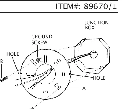
- Mounting Bracket: Hold the mounting bracket (A) so the two holes are on the left and right, with the ground screw facing outward. Pull house wires through the center hole and align the bracket holes with the junction box. Secure the bracket using the junction box screws (B). Ensure wires are not pinched.
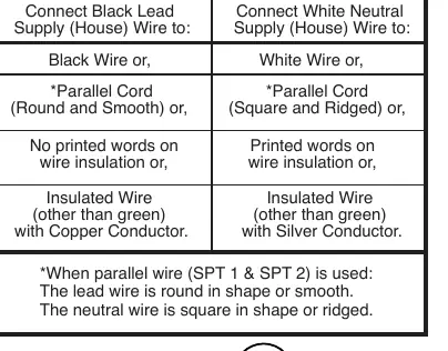
- Wiring: Strip 3/4 inch of insulation from the fixture wires. Connect the house ground wire to the fixture ground wire using the ground screw and wire nut (C). Connect the house lead wire (black) to the fixture lead wire, and the house neutral wire (white) to the fixture neutral wire using wire nuts (C). Wrap wire nuts with electrical tape for extra security.
- Backplate: Place the backplate (D) over the mounting bracket (A). Align the holes and secure the fixture to the wall using the fixture mounting screws (E).
Bulb and Shade Installation
Once the fixture is secured to the wall:
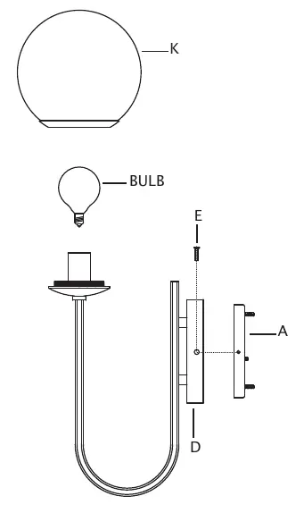
- Bulb: Screw in the recommended E12 candelabra bulb (not included). Verify the maximum wattage allowed by checking the socket label. Do not exceed the maximum wattage.
- Shade: Carefully pass the hole in the glass shade (K) over the bulb. Turn the shade clockwise to secure it in place. Do not overtighten.
Practical help
Common problems
Wires pinched between mounting bracket and wall
Ensure wires are pulled completely through the center hole of the mounting bracket before tightening screws.
Missing parts
Contact the retailer from which the product was purchased.
Bulb not fitting or incorrect brightness
Ensure you are using an E12 candelabra bulb and verify the maximum wattage marked on the socket.
Before use
- Disconnect power at the main fuse box.
- Verify all parts are present.
- Check local electrical codes.
- Ensure you have an E12 candelabra bulb.
- Confirm the junction box is compatible.
Show more Show less
Images and diagrams
- The wiring diagram illustrates the correct connection of the house ground wire to the fixture ground wire using the ground screw.
- The connection chart provides guidance for identifying house wires (black/white) versus fixture wires, including parallel cord identification.
Model compatibility
- Intended for installation in accordance with the National Electrical Code (NEC) and local code specifications.

Manual page author
Emily Carter
User documentation editor