Electronics / Monitors
User Manual for Ernitec 0070-1322A 1080P Mercury Network Camera
Quick setup guide for the Ernitec 0070-1322A 1080P Mercury Network Camera. Includes installation instructions, wiring diagrams, OSD menu operation, and mode switching procedures.
Table of contents
Manual images
Click an image to enlargeQuick guide from the manual
This document provides essential instructions for the installation and operation of the Ernitec 0070-1322A 1080P Mercury Network Camera. Before installation, ensure you have all components listed in the packing list, including the camera, screws, anchors, and screwdrivers. Always adhere to local electrical safety standards and use power adapters marked with the LPS standard.
Device structure and connections
The camera features a multi-function switch for OSD menu navigation and mode switching. The power and video cable connection requires a BNC connector for the video signal and a low-voltage power cable (12V DC or 24V AC, check the product label). Ensure no water or liquid enters the device during installation.
Operation and OSD menu
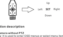
Users can access the OSD main menu using the multi-function switch keys (Up, Down, Left, Right, SET). The camera supports multiple video modes (AHD, TVI, CVBS, CVI). To switch modes, press and hold the corresponding button for 5 seconds:
- Left button: AHD mode
- Right button: TVI mode
- Up button: CVBS mode
- Down button: CVI mode
For PTZ-enabled models, press the SET button for 5 seconds to cycle through Pan/Tilt, Zoom, and Camera modes.
Installation
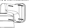
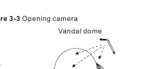
The camera can be installed on ceilings or walls. Use the provided installation sticker to mark and drill holes for the plastic anchors. For plastic domes, press down and rotate the cover counterclockwise to remove it. For vandal domes, use the T15 screwdriver to unscrew the cover. Ensure the dome cover is installed at least half an hour after the camera is powered on to prevent moisture buildup.

Maintenance and safety
Clean the device with a soft, dry cloth. For stubborn dirt, use a neutral cleanser. Do not block ventilation openings. Keep the device away from heat sources, moisture, and strong magnetic interference. If the device is installed outdoors, take appropriate insect- and moisture-proof measures.
Manufacturer information
Ernitec
Practical help
Common problems
Incorrect video mode (AHD/TVI/CVBS/CVI)
Use the OSD multi-function switch keys to switch modes. Press and hold the specific direction button (Left, Right, Up, or Down) for 5 seconds as indicated in the manual.
Moisture inside the dome
Install the dome cover at least half an hour after the camera is installed and powered on to allow for stabilization.
Focusing lever is stuck
The focusing lever is locked by default. Loosen it in a counterclockwise direction before attempting to adjust the lens angle.
Before use
- Verify all items from the packing list are present (camera, screws, anchors, T15 screwdriver).
- Confirm the power supply matches the label (12V DC or 24V AC).
- Ensure the installation surface is stable and free from vibration.
- Ground the device if installed in areas with unsteady voltage to prevent power supply damage.
- Remove the protection vinyl from the dome cover before final assembly.
Specs in practice
- 12V DC / 24V AC
- Power input requirements; verify the label on your specific product box.
- AHD/TVI/CVBS/CVI
- Selectable video output modes to ensure compatibility with your DVR/NVR.
Images and diagrams
- Figure 2-1: Shows the connection of the BNC video cable and power cable.
- Figure 2-2: Illustrates the OSD multi-function switch keys (Up, Down, Left, Right, SET).
- Figure 3-1/3-2: Demonstrates ceiling and wall mounting procedures using the installation sticker.
- Figure 3-3: Shows how to open the plastic and vandal dome covers.
Model compatibility
- Requires a DVR/NVR that supports the selected video mode (AHD, TVI, CVBS, or CVI).
- Ensure the power adapter meets LPS standards.

Manual page author
Emily Carter
User documentation editor
Prepares concise manual descriptions and highlights the most useful setup, operation, and maintenance information for readers.