Electronics / Monitors
Ernitec Electra-PoE Series PoE Injector
Quick guide for Ernitec Electra-PoE-1GB-60W and Electra-PoE-10GB-90W injectors. Includes installation diagrams, technical specifications, and troubleshooting steps.
Table of contents
Manual images
Click an image to enlargeQuick guide from the manual
This document provides essential information for the Ernitec Electra-PoE series injectors. These devices are designed to provide power and data over Ethernet (PoE) to compatible network devices such as AP routers, IP cameras, and IP phones. Ensure your network cable length does not exceed 100 meters for optimal performance.
Product Description
The industrial PoE injectors comply with IEEE 802.3af/at/bt power supply standards. They support automatic detection of PoE-compliant devices and matching power output. The devices feature a metal shell with IP20 protection grade and support 6KV surge protection.
Specifications
The series includes two models with different power capabilities:
- Electra-PoE-1GB-60W: 1 Gigabit PoE Port, 60W output.
- Electra-PoE-10GB-90W: 10 Gigabit PoE Port, 90W output.
General Specifications:
- Network Protocols: IEEE 802.3 (Ethernet), 802.3u (Fast Ethernet), 802.3ab (1000Mbps), 802.3x Flow Control, 802.3ae (10G Ethernet).
- Working Environment: Temperature -20 to 50 degrees Celsius; Storage -40 to 85 degrees Celsius; Humidity 5% to 95% (non-condensing).
- PoE Standards: IEEE 802.3af (15.4W), 802.3at (30W), 802.3bt (up to 90W).
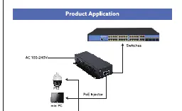
Product Application
The PoE injector is installed between the network switch and the powered device (PD). Connect the switch to the Data In port and the powered device (e.g., PTZ camera, mini PC) to the PoE Out port. Ensure the power source is connected to the AC port.
Panel Port Description
The front panel features the following interfaces:
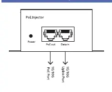
- Power Indicator: Indicates the status of the power supply.
- PoE Out Port: Delivers both power and data to the connected device.
- Data In Port: Receives data from the network switch.
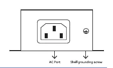
The rear panel includes the AC power input and a grounding screw for safety.
Troubleshooting
If you encounter issues, check the following:
- Power indicator light off: Verify the switch is connected to the power supply and the input voltage meets requirements.
- Access port light off: Ensure the switch and access devices are connected correctly and the network cable length is 100 meters or less.
- PoE port not powering the device: Ensure the connected device is PoE-compatible. If the device is non-PoE, the port will only transmit data. Also, verify that the power required by the device does not exceed the maximum output of the PoE port.
Manufacturer information
Ernitec
Practical help
Common problems
Power indicator light is off
Check that the power supply is connected and the input voltage matches the device requirements.
Access port indicator light is off
Ensure cables are connected securely and the total cable length does not exceed 100 meters.
PoE port does not power the device
Verify the device is PoE-compatible. If the device is non-PoE, the port will only transmit data. Also, check if the device's power requirement exceeds the injector's maximum output.
Before use
- Verify the device model (1GB-60W or 10GB-90W) matches your power requirements.
- Ensure the network cable length is 100 meters or less.
- Confirm the powered device (PD) supports IEEE 802.3af/at/bt standards.
- Ensure the power source is within the specified AC range.
- Connect the grounding screw on the rear panel for safety.
Specs in practice
- IEEE 802.3af
- Standard PoE providing up to 15.4W of power.
- IEEE 802.3at
- PoE+ standard providing up to 30W of power.
- IEEE 802.3bt
- PoE++ standard providing up to 90W of power.
Images and diagrams
- The application diagram shows the signal flow: Switch -> PoE Injector -> Powered Device (e.g., Camera).
- The panel diagram identifies the PoE Out port (for the device) and Data In port (for the switch).
- The rear panel diagram highlights the AC power input and the grounding screw location.
Model compatibility
- Compatible with IEEE 802.3af/at/bt devices.
- Not compatible with non-PoE devices for power delivery; only data transmission is supported.
- Maximum cable distance is 100 meters.

Manual page author
Michael Turner
Technical manual editor
Reviews PDF manuals for structure, safety notes, and practical product details so readers can find the right information quickly.