Tools / Welding Equipment
User Manual for ESAB Fabricator 141i Welding System
Comprehensive user manual for the ESAB Fabricator 141i 3-in-1 welding system. Includes setup instructions for MIG, TIG, and Stick welding, safety guidelines, maintenance procedures, and troubleshooting tips.
Table of contents
Manual images
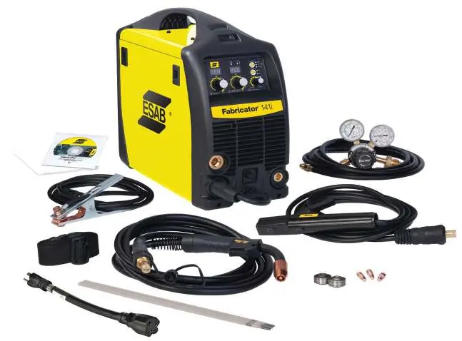
Click an image to enlargeQuick guide from the manual
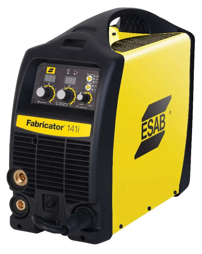
The ESAB Fabricator 141i is a 3-in-1 multi-process welding system capable of MIG (GMAW/FCAW), STICK (SMAW), and LIFT TIG (GTAW) welding. This manual provides essential instructions for safe operation, installation, and maintenance. Always read the safety precautions before operating the equipment.
Safety precautions
Welding and plasma cutting can be hazardous. Operators must be trained and familiar with the equipment. Key safety measures include:
- Always wear appropriate personal protective equipment (safety glasses, flame-proof clothing, gloves).
- Ensure the work area is well-ventilated to avoid harmful fumes.
- Do not operate in residential locations with public low-voltage supply systems due to electromagnetic compatibility issues.
- Ensure the return cable is connected securely.
- Do not use the power source for thawing frozen pipes.
Installation and setup
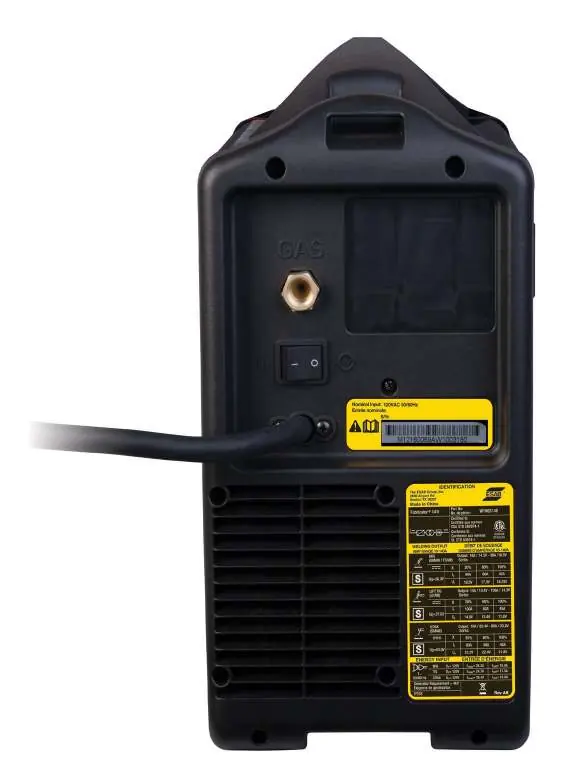
The unit requires a single-phase 115V AC power supply. Ensure the circuit is sized correctly (20A or 30A) as per the specifications. Place the unit on a horizontal surface, at least 12 inches (300mm) from walls to allow for cooling.
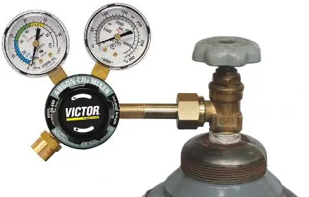
Gas regulator setup
Attach the flowmeter/regulator to the shielding gas cylinder. Ensure the inlet swivel filter is clean. Slowly open the cylinder valve to avoid pressure surges. Leak test the system before operation using an approved leak detector solution.
MIG welding setup
Connect the MIG gun to the adapter and secure it. Connect the MIG gun polarity lead to the positive terminal for solid wire, or the negative terminal for flux-cored (gasless) wire. Ensure the work lead is connected to the opposite terminal.
Stick and TIG setup
For Stick welding, connect the electrode holder to the positive terminal and the work lead to the negative terminal. For LIFT TIG, connect the TIG torch to the negative terminal and the work lead to the positive terminal. Note that the Fabricator 141i is not suited for AC TIG welding.
Operation
The front panel features digital meters for wirespeed/amperage and voltage. The multifunction control knob adjusts voltage (MIG), down slope (TIG), or arc force (Stick) depending on the selected mode. The trigger mode control allows switching between 2T (normal) and 4T (latch) modes.
Maintenance
Regularly inspect the equipment for damage. Clean the feed roll grooves frequently using a small wire brush. Do not use compressed air to clean the power source, as it may force metal particles into electrical components, causing failure.
Troubleshooting
If you encounter issues, consult the troubleshooting tables in the manual. Common issues include porosity (often due to gas flow problems or contaminants), inconsistent wire feed (check feed roll tension and conduit liner), and arc instability (check polarity and electrode size).
Manufacturer information
ESAB
Practical help
Common problems
Limited or no shielding gas flow
Check that the MIG gun connection is fully engaged, the cylinder is not empty, and the regulator is correctly adjusted.
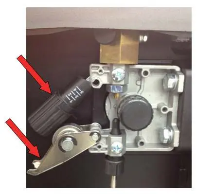
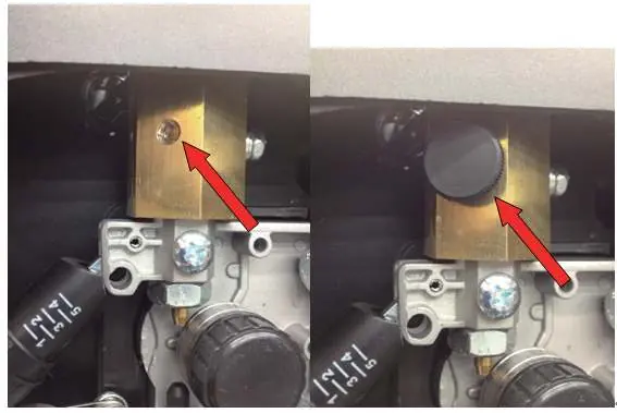
Inconsistent wire feed
Check for a clogged or kinked conduit liner, incorrect feed roll size, or improper brake tension on the spool hub.
Arc does not have a crisp sound
Verify the MIG gun polarity lead is connected to the positive (+) terminal for solid wires.
Fault indicator illuminated
The duty cycle has been exceeded. Leave the power source switched on and allow it to cool.
Before use
- Ensure the welding area is effectively ventilated.
- Verify the electrical supply is 115V AC and the circuit is sized correctly (20A or 30A).
- Check that the work clamp is securely connected to the workpiece.
- Inspect the MIG gun and cables for any damage.
- Ensure the correct feed roll is installed for the wire size being used.
Specs in practice
- OCV (Open Circuit Voltage)
- The voltage present at the output terminals when not welding (53V DC).
- Wirefeed Speed
- Controls the speed of the wire feed motor, which directly adjusts the output current in MIG mode.
Images and diagrams
- Front Panel: Displays controls for wirespeed, voltage, and process selection.
- Wire Feed Compartment: Contains the spool hub, feed rollers, and local/remote switch.
- Remote Control Socket: 8-pin connection for spool guns or remote devices.
Model compatibility
- Not suited for AC TIG welding.
- Requires 115V AC power supply.
- Compatible with 4" (100mm) and 8" (200mm) wire spools.

Manual page author
David Miller
Documentation analyst
Organizes user manual content into clear summaries, with attention to model details, product context, and everyday usability.