Tools / Welding Equipment
User Manual for Sealey MIGHTYMIG 150 MIG Welder
Quick guide for the Sealey MIGHTYMIG 150 MIG Welder. Includes assembly instructions, gas/gasless setup, maintenance procedures, and troubleshooting tips.
Table of contents
Manual images
Click an image to enlargeQuick guide from the manual
The Sealey MIGHTYMIG 150 is a professional MIG welder featuring forced air cooling and a heavy-duty transformer. This manual provides essential instructions for assembly, setup, and maintenance. Always ensure you are wearing appropriate safety gear, including a welding head shield and gauntlets, before operation.
Assembly
Before use, assemble the unit as follows:
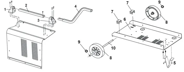
- Wheels: Drop axle brackets through the rear tray slots. Slide wheels onto the axle, secure with circlips, and pass the axle through the brackets.
- Front Foot: Align the foot with the holes on the underside of the tray and secure with three self-tapping screws.
- Handle: Attach the rear handle bracket to the casing. Slide the handle into the bracket, attach the front bracket, and secure the handle extension with a self-tapping screw.
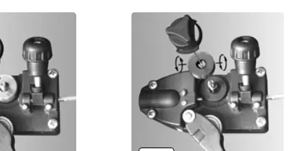
Preparation and Wire Setup
To fit a reel of wire:
- Open the side compartment using the black catch.
- Rotate the butterfly nut anti-clockwise to remove it and the pressure disc, leaving the spring on the spindle.
- Place the wire reel onto the spindle, ensuring it feeds from the top in a forward direction.
- Replace the pressure disc and butterfly nut. Do not overtighten; the reel should have a mild braking effect.
- Feed the wire through the guide and into the torch liner.
Wire Tension: Set the tension by turning the wire lock screw. Too little or too much tension causes poor wire feed. Test by slowing the wire between gloved fingers; if the roller skids, the tension is correct.
Control Panel
The control panel features:
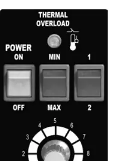
- Power Switch: Green light indicates power is ON.
- Current Switches: MIN, MAX, 1, and 2 switches provide four power levels (MIN/1, MIN/2, MAX/1, MAX/2).
- Wire Speed Knob: Adjusts the speed of the wire feed. Generally, higher current requires higher wire speed.
- Thermal Overload Light: Illuminates if the duty cycle is exceeded. The welder will automatically reset after cooling (approx. 5-10 minutes).
Gas vs. Gasless Operation
The welder is supplied set up for gasless mode but can be converted to gas welding.
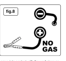
- Gasless Mode: Ensure the earth clamp is connected to the POSITIVE (+) terminal and the torch lead is connected to the NEGATIVE (-) terminal.
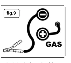
- Gas Mode: Requires a gas conversion kit (120.802032). Connect the earth clamp to the NEGATIVE (-) terminal and the torch lead to the POSITIVE (+) terminal.
Maintenance
- Wire Feed Unit: Clean rollers weekly to remove dust.
- Torch Liner: If the liner is blocked or damaged, it must be replaced. Remove the torch cable clamp, open the torch case, disconnect the liner, and pull it out. Insert the new liner and reassemble.
- Consumables: Keep the gas cup and contact tip free from spatter to prevent short circuits. Use anti-spatter spray.
Manufacturer information
Sealey Group
Practical help
Common problems
Power source stops
Overheating protection activated due to overload. Wait about 15 minutes for the transformer to cool.
Wire does not feed
Check wire tension, clean the torch liner with compressed air, or replace the gas cup/tip if defective.
Porous weld
Check gas supply, clean joints of paint/rust, or adjust torch distance to 8-10mm from the workpiece.
Unstable arc
Check settings, clean the weld area, or replace a worn gas cup.
Before use
- Inspect power leads and plugs for wear or damage.
- Ensure the work area is well-ventilated and free of flammable materials.
- Wear a welding head shield and safety gauntlets.
- Verify polarity is set correctly for the chosen welding mode (Gas vs Gasless).
- Ensure the workpiece is clean and free of paint, rust, or grease.
Specs in practice
- Welding Current
- 30-150A.
Images and diagrams
- Assembly diagram shows the correct placement of wheels, axle, and handle components.
- Control panel diagram identifies the power switch, current switches, and wire speed knob.
- Polarity diagrams illustrate the correct terminal connections for gas and gasless welding modes.
Model compatibility
- Requires 230V power supply.
- Gas conversion kit (120.802032) is required for gas welding.
- Supports 0.6mm or 0.8mm wire for gas welding.

Manual page author
Michael Turner
Technical manual editor
Reviews PDF manuals for structure, safety notes, and practical product details so readers can find the right information quickly.