Tools / Welding Equipment
User Manual for Sealey 150A Professional Gas/No-Gas MIG Welder
Comprehensive user guide for the Sealey 150A Professional Gas/No-Gas MIG Welder (MIGHTYMIG150.V3). Includes assembly, wire installation, gas conversion, maintenance, and troubleshooting procedures.
Table of contents
Manual images
Click an image to enlargeQuick guide from the manual
This manual provides essential instructions for the safe operation and maintenance of the Sealey 150A MIG Welder. Key tasks include assembling the unit, installing the wire spool, setting up for gas or gasless welding, and performing routine maintenance on the torch and feed rollers. Always ensure the welder is disconnected from the power supply before performing any maintenance.
Safety
Electrical Safety: Inspect all cables and plugs for wear before use. Use an RCD (Residual Current Device). Do not pull the unit by the cable. Ensure the voltage rating matches your power supply. If using a generator, it must be self-regulating and stable.
General Safety: Do not weld in rain or snow. Wear appropriate protective gear, including a welding mask, gloves, and body protection. Keep the work area clean and free of flammables. Do not weld near medical implants due to electromagnetic fields.
Gas Safety: Store cylinders vertically and secure them. Do not expose cylinders to temperatures above 50°C. Keep cylinders cool and do not puncture or damage them.
Assembly
Wheels and Foot: Attach the axle brackets to the rear tray, slide the axle through, and secure the wheels with circlips. Attach the front foot to the underside of the tray using the provided screws.
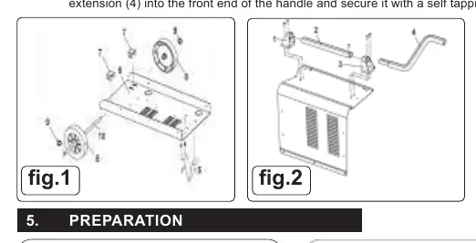
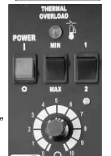
Handle: Attach the rear handle bracket to the top casing. Slide the handle into the bracket, attach the front bracket, and secure the handle extension with a self-tapping screw.
Preparation
Fitting a Wire Reel: Open the side compartment. Remove the pressure disc and knob from the spindle. Place the wire reel onto the spindle, ensuring the wire feeds from the top. Replace the pressure disc and tighten it to provide a mild braking effect; do not overtighten.
Wire Tension: Correct tension is crucial. Adjust the wire lock screw to increase or decrease tension. Test by slowing the wire between gloved fingers; if the roller skids, the tension is correct.
Control Panel
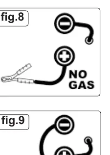
The control panel features a thermal overload light, power on/off switch, current switches (MIN/MAX and 1/2), and a wire speed control knob. If the thermal overload light illuminates, the unit has exceeded its duty cycle; allow it to cool for 5-10 minutes.
Gasless and Gas Operation
Gasless Operation: Ensure the earth clamp is connected to the POSITIVE (+) terminal and the torch lead to the NEGATIVE (-) terminal.
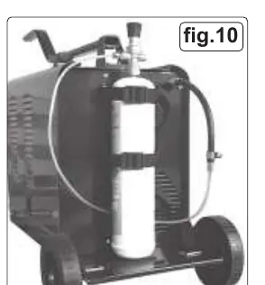
Gas Conversion: To convert to MIG welding, you will need a gas conversion kit (Model No. 120.802032), a gas bottle, and regular wire. Ensure the polarity is reversed: earth clamp to NEGATIVE (-) and torch lead to POSITIVE (+).
Maintenance
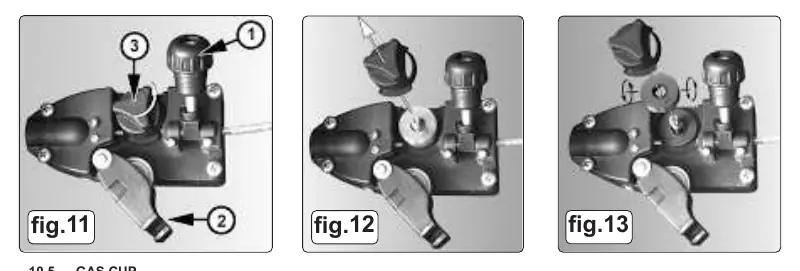
Wire Feed Unit: Regularly clean the feed roller groove and remove dust. Ensure the groove size matches the wire diameter (0.6mm or 0.8mm) by flipping the roller if necessary.
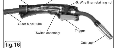
Torch and Liner: Keep the gas cup free of spatter using anti-spatter spray. If the wire feed is poor, clean the liner with compressed air or replace it if damaged. To replace the liner, remove the torch cable clamp, locking ring, and screws to access the inner assembly.
Troubleshooting
If the power source stops, it may be due to overheating; wait for the transformer to cool. If there is no weld current, check for bad connections or broken leads. If wire feed is uneven, check for dirt in the liner, clogged feed roller, or improper tension.
Manufacturer information
Sealey Group
Practical help
Common problems
Power source stops
Overheating protection activated; wait for the transformer to cool (approx. 15 minutes).
No weld current
Check for bad connection between clamp and workpiece, or broken earth/torch leads.
Wire does not feed
Check pressure roller adjustment, clean torch liner with compressed air, or replace defective gas cup/tip.
Porous weld
Check gas supply, ensure gas cup is not clogged, or adjust torch distance (8-10mm from workpiece).
Before use
- Inspect power supply leads, plugs, and connections for wear.
- Ensure the voltage rating matches your power supply.
- Check that the workpiece is clean and secured.
- Verify polarity is set correctly for gas or gasless operation.
- Ensure the wire feed roller groove matches the wire size.
Specs in practice
- Welding Current
- 30-150A range.
- Absorbed Power
- 4.5kW.
Images and diagrams
- Fig 1 & 2: Assembly of wheels, foot, and handle.
- Fig 3, 4, 5: Wire spool installation and pressure disc adjustment.
- Fig 7: Control panel layout including overload light and wire speed.
- Fig 8 & 9: Polarity connection for gasless vs gas operation.
- Fig 11-13: Feed roller maintenance and groove selection.
Model compatibility
- Requires 16A supply for full capacity.
- Compatible with 0.6mm or 0.8mm wire.
- Gas conversion requires separate kit (120.802032).

Manual page author
David Miller
Documentation analyst
Organizes user manual content into clear summaries, with attention to model details, product context, and everyday usability.