Lighting / Fixtures
Installation Manual for Eurofase 35697-015 Bathroom Wall Light
Complete installation guide for the Eurofase 35697-015 LED bathroom wall light. Includes wiring diagrams, safety precautions, required tools, and technical specifications.
Quick answers from the manual
Quick answer
- This manual provides installation instructions for the Eurofase 35697-015 LED wall light, including wiring diagrams and safety requirements. p. 1, 2
Key actions
- Turn off power at the circuit breaker before starting installation. p. 1
- Connect the fixture wires to the junction box wires (Black to Black, White to White, Ground to Ground). p. 2
Problems and fixes
No ground wire in junction box
Attach the bare copper fixture wire to the green ground screw on the crossbar.
p. 1Show 2 more answers Show less
Technical specifications
| Parameter | Value | Meaning | Pages |
|---|---|---|---|
| Power | 20W MAX | Maximum wattage | p. 2 |
| Voltage | 120V | Operating voltage | p. 2 |
Where to find it in the PDF
- Safety and Tools p. 1
- Wiring Diagram and Parts p. 2
Table of contents
Quick Guide from the Manual
This document provides installation instructions for the Eurofase 35697-015 LED wall light. The installation requires approximately 20 minutes. Important: Always disconnect power at the circuit breaker or fuse box before beginning any electrical work. Installation should be performed by a qualified electrician in accordance with local and national electrical codes.
Required Tools
- Flathead screwdriver
- Phillips screwdriver
- Pliers
- Electrical tape
- Wire cutters
- Wire strippers (helpful)
- Ladder (helpful)
Installation and Wiring
Follow the numerical progression outlined in the manual for assembly.
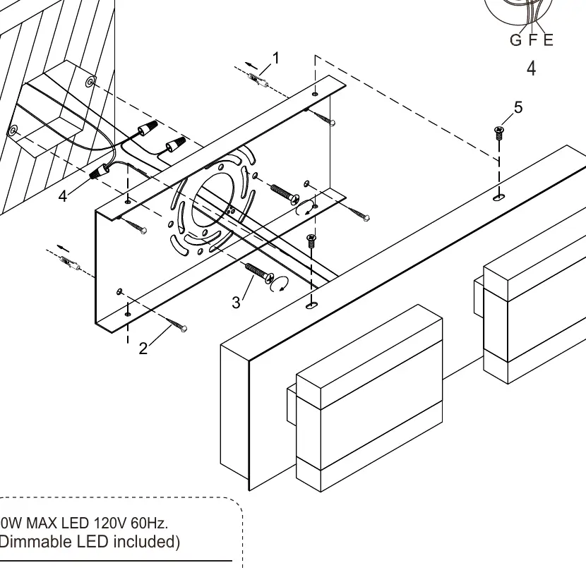
- Power Off: Ensure the power is completely disconnected at the circuit breaker.
- Wiring Connections: Use CSA or UL listed wire connectors suitable for the gauge and number of conductors.
- Grounding: Connect the junction box grounding wire (green or bare copper) to the bare copper wire from the fixture. If the junction box lacks a ground wire, attach the fixture's bare copper wire to the green ground screw on the crossbar.
- Circuit Wiring: Connect the black wire (L) from the junction box to the black wire (L) from the fixture. Connect the white wire (N) from the junction box to the white wire (N) from the fixture.
Technical Specifications
- Power: 20W MAX LED
- Voltage: 120V
- Frequency: 60Hz
- Features: Dimmable LED included
Practical help
Common problems
Fixture does not turn on after installation
Verify that the circuit breaker is on and that all wire connections (Black-to-Black, White-to-White) are secure and properly connected.
Junction box has no ground wire
Attach the bare copper fixture wire directly to the green ground screw located on the crossbar.
Before use
- Turn off power at the circuit breaker or fuse box
- Ensure you have a flathead and Phillips screwdriver, pliers, and wire cutters
- Verify that the junction box is compatible with the fixture
- Confirm the installation is performed by a qualified electrician
Show more Show less
Images and diagrams
- The wiring diagram illustrates the connection of the black (L) and white (N) wires using wire connectors.
- The diagram shows the grounding connection between the junction box and the fixture.
- The mounting hardware (screws) is shown attaching the fixture to the junction box.
Model compatibility
- Designed for 120V 60Hz electrical systems.
- Requires a junction box for mounting.

Manual page author
Emily Carter
User documentation editor