Toys / RC Models & Drones
User Manual for Hobbywing Platinum 150A V5.1 Brushless ESC
Quick guide for the Hobbywing Platinum 150A V5.1 Brushless Electronic Speed Controller. Includes wiring diagrams, throttle calibration, programming instructions, and speed governor setup.
Table of contents
Manual images
Click an image to enlargeQuick Guide
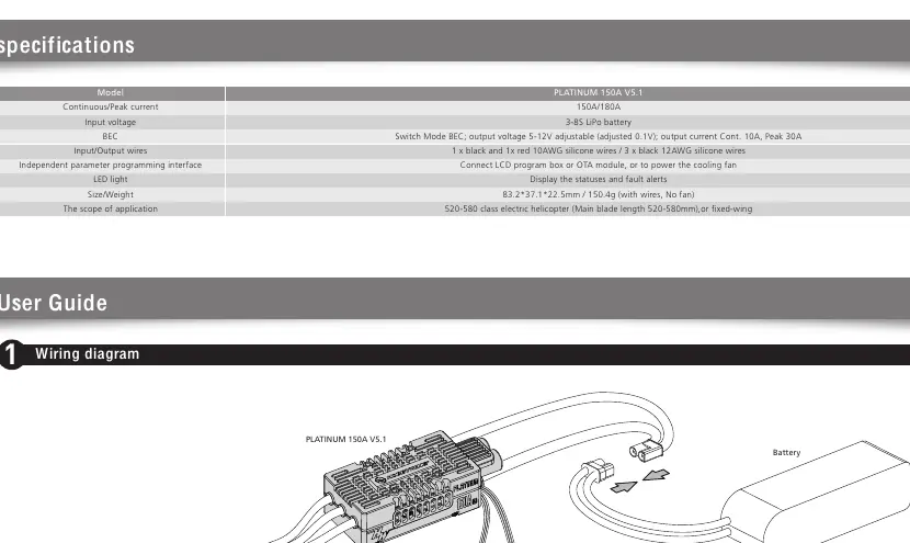
The Hobbywing Platinum 150A V5.1 is a high-performance brushless electronic speed controller designed for 520-580 class electric helicopters and fixed-wing aircraft. Key requirements for operation include proper wiring, initial throttle range calibration, and configuration of the speed governor mode. Always ensure the battery is disconnected after use to prevent discharge.
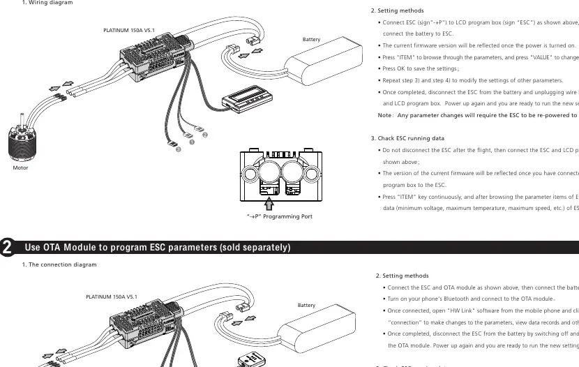
Wiring and Connections
Proper wiring is critical for safe operation. Ensure all connections are secure to avoid short circuits.
- Motor: Connect the three motor wires to the ESC output.
- Battery: Connect the battery to the ESC input.
- Receiver: Connect the throttle signal wire (white, red, black) to the receiver throttle channel.
- RPM Signal: Connect the yellow RPM signal wire to the external device (e.g., Flybarless system gyro).
- BEC Output: The additional BEC output wire (red, brown) should be plugged into a dedicated battery channel or any available receiver channel.
- External Capacitor (Cappack): If using high-power servos, connect the optional external capacitor module in parallel to the BEC output end to prevent overload.
Boot and Throttle Calibration
The ESC must be calibrated to your transmitter's throttle range before the first use or if the transmitter is replaced.
- Turn on the transmitter and set the throttle to the 100% position.
- Connect the battery to the ESC. The motor will sound "123" to indicate power is on.
- Within 5 seconds, move the throttle stick to the minimum position.
- The ESC will sound a beep to indicate the number of lithium cells, followed by a final beep indicating the system is ready.
ESC Programming
Parameters can be customized using the Multifunction LCD Program Box or the OTA Module (sold separately).
- LCD Program Box: Connect the ESC to the program box using the "-+P" port. Use the "ITEM" and "VALUE" buttons to navigate and save settings.
- OTA Module: Connect the module to the ESC, enable Bluetooth on your phone, and use the "HW Link" app to adjust parameters and view data records.
Speed Governor Function
The ESC features advanced speed governing modes (Elf, Store, External). To use these, you must perform RPM standardization:
- Ensure the main blade pitch is 0° during standardization.
- Use a fully charged battery.
- The ESC will establish a "Motor RPM-Throttle Amount" curve.
- In "Store Governor" mode, the ESC saves this curve, allowing for consistent RPM across different flights without re-standardizing, provided the battery cell count remains the same.
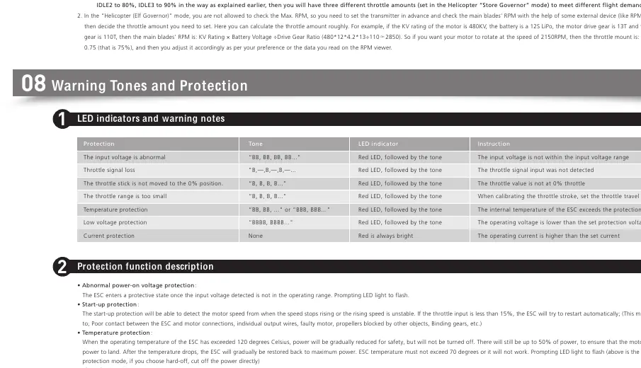
Protection and Warning Tones
The ESC includes multiple protection features to prevent damage:
- Abnormal Voltage: Input voltage is outside the operating range.
- Throttle Signal Loss: Output is switched off if signal is lost for >0.25 seconds.
- Temperature Protection: Power is gradually reduced if the temperature exceeds 120°C.
- Overloading/Current Protection: Power is cut off if current exceeds limits.
- Start-up Protection: Detects if the motor fails to start or speed is unstable.
Manufacturer information
Hobbywing
Practical help
Common problems
Throttle signal loss
Check receiver connection and signal wire integrity.
Input voltage abnormal
Ensure battery voltage is within the 3-8S LiPo range.
Throttle range too small
Re-calibrate the throttle range using the transmitter.
Temperature protection triggered
Allow the ESC to cool down; check for overloading or blocked propellers.
Before use
- Ensure all wires are properly soldered and secured.
- Verify battery cell count matches ESC settings.
- Calibrate throttle range before the first flight.
- Ensure main blade pitch is 0° during RPM standardization.
- Check that the throttle curve is set to default before calibration.
Specs in practice
- Continuous/Peak Current
- Rated for 150A continuous and 180A peak current.
- Input Voltage
- Supports 3-8S LiPo battery packs.
Images and diagrams
- Wiring Diagram: Illustrates connections for motor, battery, receiver, and RPM signal.
- Cappack Wiring: Shows how to connect the optional external capacitor module for BEC stability.
Model compatibility
- Designed for 520-580 class electric helicopters or fixed-wing aircraft.

Manual page author
Emily Carter
User documentation editor
Prepares concise manual descriptions and highlights the most useful setup, operation, and maintenance information for readers.