Toys / RC Models & Drones
FMS 1300mm PA-18 Quick Start Guide
Quick start guide for the FMS 1300mm PA-18 RC airplane. Includes assembly instructions, wiring diagrams, transmitter setup, and essential pre-flight safety checklists.
Table of contents
Manual images
Click an image to enlargeQuick guide from the manual
This document provides essential assembly, setup, and safety information for the FMS 1300mm PA-18 RC airplane. It is intended to help users complete the initial setup and pre-flight checks efficiently. For advanced configurations or troubleshooting, please refer to the full manual available via the QR code on the cover.
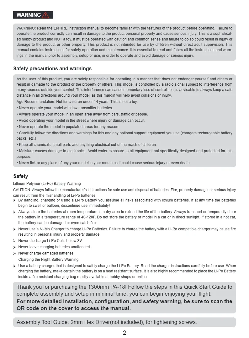
Safety precautions
- Age Recommendation: Not for children under 14 years. This is not a toy.
- Flying Environment: Operate in an open area away from people, buildings, traffic, and power lines.
- Li-Po Battery Safety: Always follow manufacturer instructions. Never use a Ni-MH charger for Li-Po batteries. Never leave charging batteries unattended. Store batteries at room temperature (40-120F). If a battery swells or balloons, discontinue use immediately.
- General Safety: Keep small parts and electrical components out of reach of children. Moisture can damage electronics.
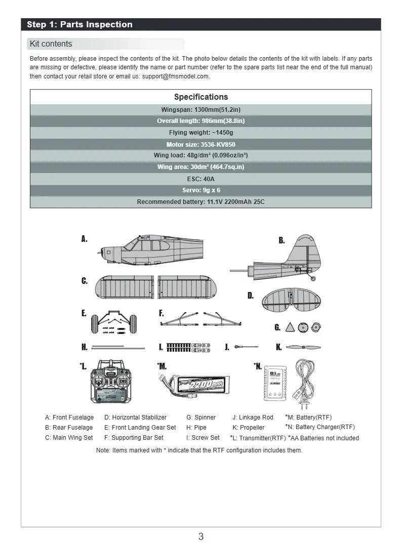
Specifications
- Wingspan: 1300mm (51.2in)
- Overall length: 986mm (38.8in)
- Flying weight: ~1450g
- Motor: 3536-KV850
- ESC: 40A
- Recommended battery: 11.1V 2200mAh 25C
Assembly and wiring
Before assembly, inspect all kit contents. You will need a 2mm Hex Driver (not included) for tightening screws.
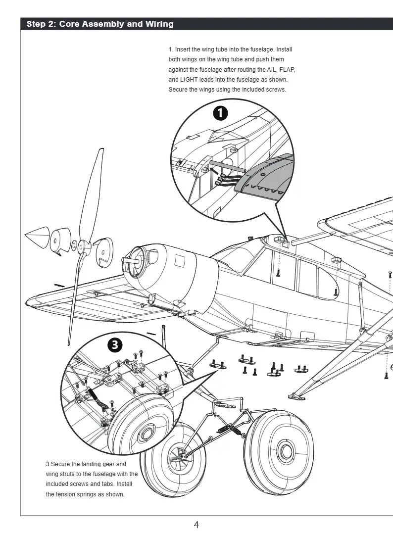
- Wing Installation: Insert the wing tube into the fuselage. Install both wings on the tube and push them against the fuselage. Route the AIL, FLAP, and LIGHT leads into the fuselage and secure the wings with the included screws.
- Landing Gear: Secure the landing gear and wing struts to the fuselage using the included screws, tabs, and tension springs.
- Struts: Secure the supporting struts on the main wing using the included R-clips.
- Tail Assembly: Route the RUD and ELE servo leads into the front fuselage. Secure the rear fuselage with screws at the top and bottom. Ensure the servo is in the neutral position and install the elevator pushrod to the control horn.
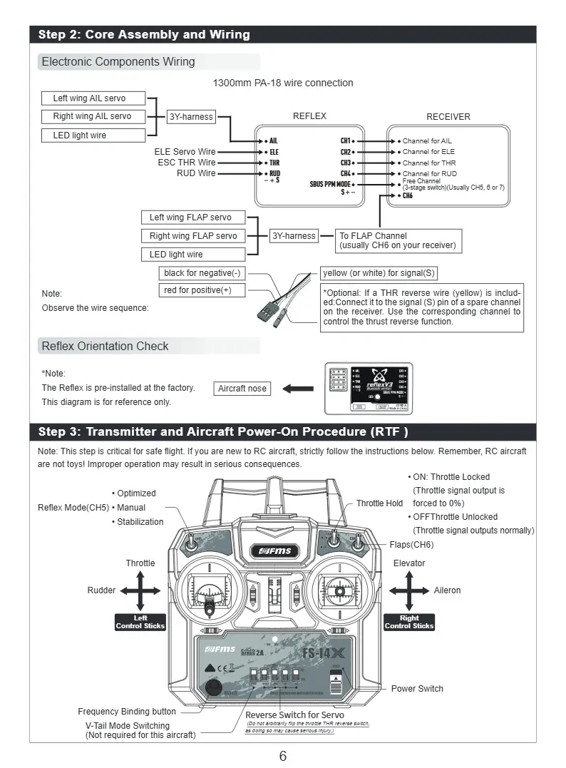
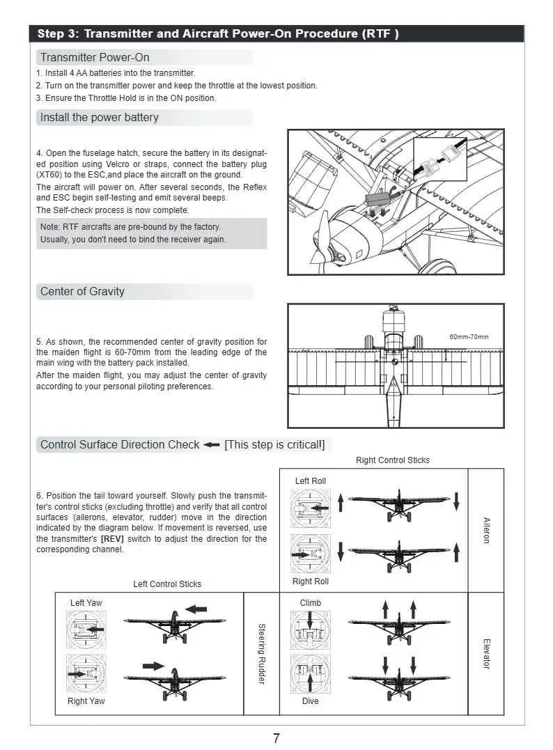
Transmitter and power-on procedure
Ensure the transmitter is powered on with the throttle at the lowest position and the Throttle Hold in the ON position. Open the fuselage hatch, secure the battery, and connect the XT60 plug to the ESC. The aircraft will power on and perform a self-check. Verify the center of gravity is 60-70mm from the leading edge of the main wing with the battery installed.
First flight checklist
Perform these checks before every flight:
- Environment: Wind speed is below Beaufort Scale 3.
- Structure: Verify all structural components (screws, rods, struts) are securely installed.
- Battery: Aircraft battery must be fully charged (e.g., 12.6V for 3S).
- Signal: Transmitter and receiver have established communication.
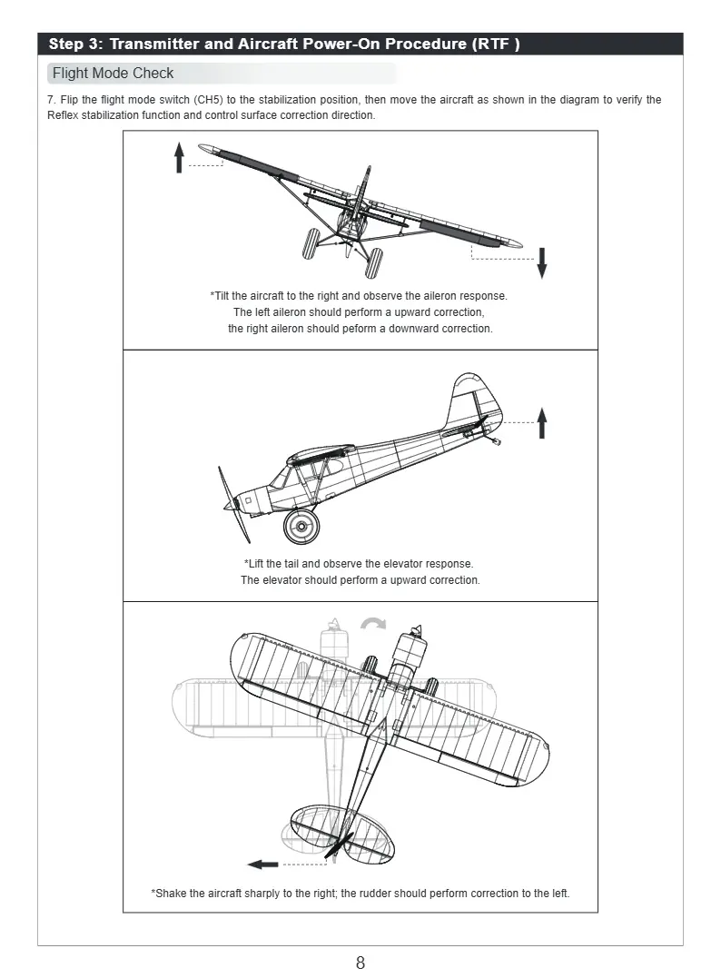
- Control Surfaces: All surfaces deflect in the correct direction.
- Center of Gravity: Falls within the recommended range.
Manufacturer information
FMS Model
Practical help
Common problems
Control surfaces moving in the wrong direction
Adjust the corresponding channel in the transmitter's [Servo Reverse] menu.
Binding failed
Refer to the [Binding and Calibration] section in the full transmitter manual.
Before use
- Ensure wind speed is below Beaufort Scale 3.
- Verify all structural components (screws, rods, struts) are securely installed.
- Ensure battery is fully charged (12.6V for 3S).
- Confirm transmitter and receiver have established communication.
- Verify all control surfaces deflect in the correct direction.
- Check that the center of gravity is within the recommended range.
Specs in practice
- Recommended Battery
- 11.1V 2200mAh 25C
Images and diagrams
- Wiring diagram illustrates connections for AIL, ELE, THR, RUD, and FLAP servos to the receiver.
- Transmitter diagram shows control stick functions (Throttle, Rudder, Elevator, Aileron) and switch positions.
Model compatibility
- Not for children under 14 years.
- Requires 2mm Hex Driver (not included) for assembly.

Manual page author
Emily Carter
User documentation editor
Prepares concise manual descriptions and highlights the most useful setup, operation, and maintenance information for readers.