Electronics / Networking
QuickStart Guide for Fortinet FortiAP 234G Wireless Access Point
A comprehensive guide for the Fortinet FortiAP 234G. Includes setup options, installation instructions for wall and pole mounting, waterproof cabling procedures, and interface details.
Quick answers from the manual
Quick answer
- The FortiAP 234G is a wireless access point. Default login is 192.168.1.2, username 'admin', password 'leave blank'. p. 4
Key actions
- Setup via PoE p. 6
- Factory Reset p. 6
First start
- Accessing the device p. 4
Show 2 more answers Show less
Maintenance and reset
- Reset button usage p. 6
Where to find it in the PDF
- QuickStart Guide p. 1
- Package Contents p. 5
- Installation p. 8, 9
Table of contents
Manual images
Click an image to enlargeQuick guide from the manual
The FortiAP 234G is a wireless access point designed for various deployment scenarios. To begin, ensure you have the necessary mounting hardware and an Ethernet cable. The device supports PoE (Power over Ethernet) and can be configured via a direct connection or the FortiLAN Cloud. Default login credentials are provided for initial setup.
Package Contents
- FortiAP 234G Device
- QuickStart Guide
- Mounting Kit (2x pole straps, 4x mounting bolts, 8x screws, 1x grounding cable and screw)
- Wall Mount Bracket
- Pole Mount Bracket
- PoE Injector and AC Cord (100V-220V AC input, 54V DC output)
Setup Options
PoE Installation: Connect the device to a PoE injector or a FortiGate PoE port using an Ethernet cable.
Direct Connection: Connect the FortiAP LAN port to a computer using an Ethernet cable. Access the device at 192.168.1.2 (Username: admin, Password: leave blank).
FortiLAN Cloud: Log in to your FortiCloud account, navigate to Inventory, and import the AP Key and Cloud Key found on the device sticker.
Network Connection: Connect the FortiAP to the same network as the FortiGate. Pre-authorize the FortiAP on your FortiGate or wait for it to appear on the Managed FortiAP page in FortiOS.
Installation
Wall Installation:
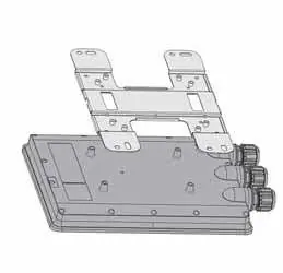
- Mark the location of the mounting bolts using the wall mount bracket.
- Drill holes and hammer the bolts into the drilled holes.
- Attach the wall mount bracket to the device using the provided mounting screws.
- Secure the device on the wall using the mounting bolts.
Pole Installation:
- Attach the wall mount bracket, then the pole mount bracket to the device using the provided mounting screws.
- Loop the pole straps through the bracket slots, then around the pole.
- Tighten the straps.
Waterproof Cabling
The device includes IP67 rated Ethernet cable glands. Follow these steps:
- Unscrew the sealing nut from the panel connector and remove the seal and claw.
- Thread the RJ45 plug through the sealing nut, then the panel connector.
- Wrap the seal and claw around the cable between the sealing nut and connector.
- Insert the RJ45 plug into the port and screw the panel connector onto the threads.
- Slide the seal and claw along the cable into the panel connector.
- Threat the coupling ring onto the panel connector and tighten it.
Interfaces
LED Status:
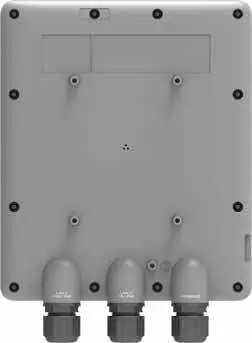
- Power: Green (Powered on, connected to controller), Amber (Powered on, not connected), Off (Powered off).
- WiFi: Green (SSID broadcasting), Blinking Green (Data activity), Off (WiFi not broadcasting).
- LAN: Green (Connected), Blinking Green (Data activity), Off (Not connected).
Ports:
- LAN1 / PoE (RJ-45): 2.5 Gbps 802.3at PoE Ethernet interface.
- LAN2 / PoE (RJ-45): 1 Gbps Ethernet interface.
- CONSOLE (RJ-45): CLI management; Reset button located above the port.
Safety
Operating temperature is -30°C to 60°C. Ensure the device is installed in a Restricted Access Location. The device is intended to be supplied by a Listed Direct Plug-in power unit marked LPS or Class 2 and rated 54Vdc, 0.6A from PoE source.
Manufacturer information
Fortinet, Inc.
Practical help
Common problems
Device not broadcasting WiFi
Check if the device is powered on and successfully connected to a controller.
Need to factory reset the device
Press and hold the reset button for 10 seconds.
Before use
- Verify all package contents are present.
- Ensure you have an Ethernet cable (not included).
- Check that the installation location is within the operating temperature range (-30°C to 60°C).
- Ensure you have access to the FortiCloud portal if using cloud management.
Show more Show less
Images and diagrams
- Wall mounting requires drilling holes and using the provided bolts.
- Pole mounting uses straps looped through the bracket slots.
- Waterproof cabling requires specific assembly of the gland components (sealing nut, seal, claw) to ensure an IP67 seal.
Model compatibility
- Requires 802.3at PoE injector or FortiGate PoE port.
- Compatible with FortiLAN Cloud for management.

Manual page author
Michael Turner
Technical manual editor