Power / Solar Inverters
Installation Guide for Fox Ess 0.7-3.3kW Single Phase Inverter
Quick installation guide for the Fox Ess 0.7-3.3kW single-phase inverter. Includes mounting instructions, AC/DC wiring steps, cable specifications, and startup procedures.
Table of contents
Manual images
Click an image to enlargeQuick guide from the manual
This document provides essential instructions for the installation and setup of the Fox Ess 0.7-3.3kW single-phase inverter. It covers the physical mounting, electrical wiring (AC and DC), and the initial startup procedure. Ensure all local electrical codes and safety regulations are followed during installation.
Packing List
Before starting, verify that the following components are included in the package:
- Inverter
- Wall bracket
- DC connectors (F/M)
- AC connector and unlock tool
- Expansion tubes and screws
- DC pin contacts
- Earth terminal
- Communication connector and unlock tool
- Optional items: CT, WiFi/LAN/GPRS module, Meter
Inverter Installation
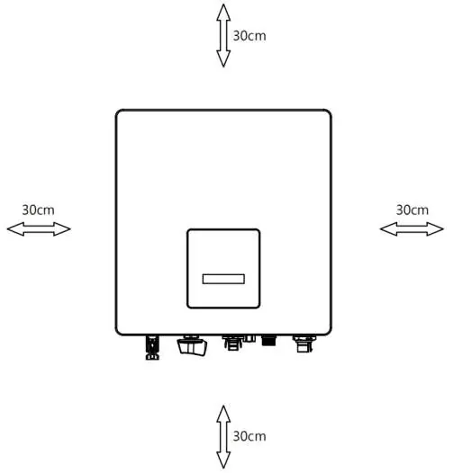
The inverter must be installed with sufficient clearance to ensure proper ventilation and maintenance access. Maintain a minimum distance of 30cm on all sides (left, right, top, bottom, and front).
Mounting Steps:
- Choose a suitable location on the wall.
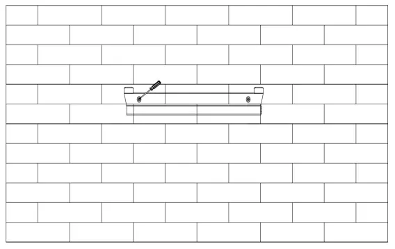
- Place the bracket against the wall and mark the positions for the two holes.
- Drill holes with an electric drill (ensure they are at least 50mm deep).
- Insert expansion tubes and tighten them.
- Secure the bracket to the wall using the expansion screws.
- Hang the inverter over the bracket, ensuring the mounting grooves on the back are properly fixed with the bracket bars.
Wiring Steps
AC Wiring:
Ensure the correct cable size and micro-breaker are used based on the model:
- 0.7kW - 1.5kW models: Use 2.5mm² cable and a 16A micro-breaker.
- 2.0kW - 3.3kW models: Use 4mm² cable and a 25A micro-breaker.
AC Connector Assembly:
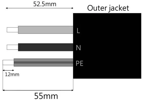
- Trim wires: 52.5mm for L/N/PE, with 12mm of insulation removed from ends.
- Separate the AC plug into three parts.
- Slide the cable nut and back shell onto the cable.
- Insert wires into the connector, push the threaded sleeve into the socket, and tighten the cap until it clicks.
DC Wiring:
- Turn off the DC switch.
- Use 12 AWG wire for PV module connection.
- Trim 6mm of insulation from the wire end.
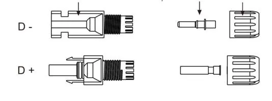
- Assemble the DC connector by inserting the striped cable into the pin contact, ensuring all strands are captured.
- Crimp the pin contact using crimping pliers.
- Insert the pin contact through the cable nut into the plug until a click is heard.
Grounding
Connect the grounding wire to the inverter using the ground screw provided on the unit.
Startup Procedure
- Check that all connections are secure and correct.
- Turn on the external DC and AC breakers.
- Turn the DC switch to the ON position.
- The inverter will start automatically once the PV panels generate sufficient energy. The LED will turn green, and the LCD screen will display the main interface.
Note: During the first startup, verify that the country code is set correctly to local settings. You can set the time on the inverter using the button or the app.
Practical help
Common problems
Inverter does not start
Ensure PV panels are generating sufficient energy, external DC/AC breakers are ON, and the DC switch is in the ON position.
Connector assembly failure
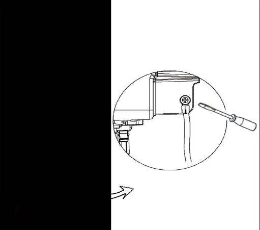
Ensure you hear a 'click' when seating the pin contact into the plug. If the connector is locked, use the unlock tool or a small screwdriver to press the bayonet out.
Incorrect country settings
Check the country code during the first startup to ensure it matches local requirements.
Before use
- Verify all components from the packing list are present.
- Ensure the wall surface is suitable for mounting the bracket.
- Confirm 30cm clearance on all sides of the inverter.
- Select the correct cable size (2.5mm² or 4mm²) based on your inverter model.
- Ensure you have the necessary tools: electric drill, crimping pliers, and screwdriver.
Specs in practice
- AC Cable (0.7-1.5kW)
- Requires 2.5mm² cross-section cable.
- AC Cable (2.0-3.3kW)
- Requires 4mm² cross-section cable.
- Micro-Breaker (0.7-1.5kW)
- Requires 16A rating.
- Micro-Breaker (2.0-3.3kW)
- Requires 25A rating.
- DC Wire Stripping
- Remove 6mm of insulation from the wire end.
Images and diagrams
- Clearance diagram: Illustrates the 30cm minimum distance required around the inverter.
- AC Wiring diagram: Shows the stripping lengths (52.5mm total, 12mm insulation) and wire color coding (L: Brown/Red, N: Blue/Black, PE: Yellow/Green).
- DC Connector diagram: Shows the assembly of the plug, pin contact, and cable nut.
Model compatibility
- Compatible with optional CT, WiFi/LAN/GPRS, and Meter accessories.

Manual page author
Michael Turner
Technical manual editor
Reviews PDF manuals for structure, safety notes, and practical product details so readers can find the right information quickly.