Power / Solar Inverters
User Manual for Fox ESS G Series Solar Inverter
Quick guide for the Fox ESS G Series solar inverter. Includes installation steps, wiring diagrams, operation instructions, troubleshooting, and technical specifications for models G7-VB through G10.5-VB.
Table of contents
Manual images
Click an image to enlargeQuick guide from the manual
This manual provides essential information for the installation, operation, and maintenance of the Fox ESS G Series solar inverters (models G7-VB to G10.5-VB). The inverter is designed for single-phase grid connection and features dual MPP trackers. Installation must be performed by qualified personnel only.
Safety and Precautions
- Qualified Personnel: All installation and maintenance must be carried out by licensed electricians.
- Environment: Do not install in areas with flammable substances, high humidity, or extreme temperatures. Ensure adequate ventilation.
- Electrical Safety: Always wait 5 minutes after disconnecting power before opening the inverter to allow for discharge.
- Surge Protection: External surge protection devices (SPD type 2) are recommended for both DC and AC sides.
Installation
The inverter must be installed on a wall with a slope within ±5°. Ensure a minimum clearance of 300mm on all sides for cooling.

Installation Steps
- Fix the mounting bracket to the wall using the provided expansion screws.
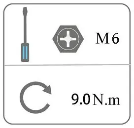
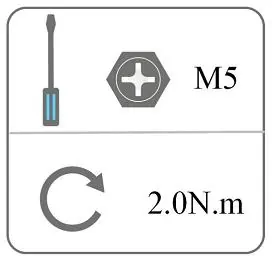
- Mount the inverter onto the bracket and secure it with the M5 screw.
Wiring
- PV Connection: Ensure PV module voltage is less than 600V. Use 6mm² wire for DC connections. Ensure correct polarity.
- AC Connection: Use the provided AC connector. Ensure the grid voltage matches the inverter specifications (220/230/240V).
- Earth Connection: Connect the grounding screw to the protective earth.
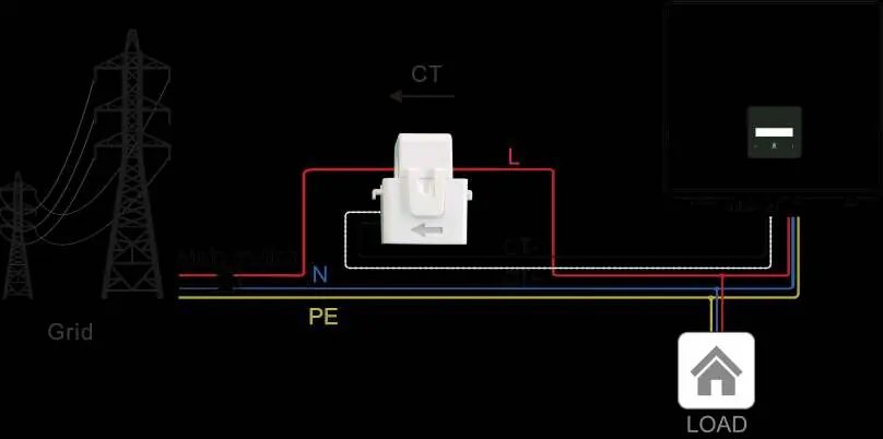
- Communication: Optional WiFi/4G/LAN modules can be installed. Export limitation requires a CT or Smart Meter installed on the grid side.
Operation
The inverter features an LCD screen and a touch key for interaction.
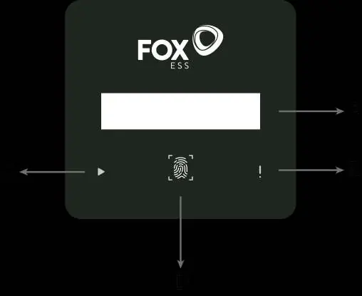
- Short press (<1s): Navigate to the next item.
- Long press (>2s): Enter/Confirm selection.
- States: The inverter displays 'Waiting', 'Checking', or 'Normal' status.
Maintenance and Troubleshooting
Regular maintenance includes checking cooling fins for dust, inspecting wire integrity, and verifying indicator status every 6 months.
Alarm List
- DCI Fault: Disconnect PV, wait for LED to switch off, and reconnect.
- Grid Lost Fault: Check grid connection, wires, and interface.
- Isolation Fault: Check impedance between PV and ground (should be >1Mohm).
- Over Temp: Check if the environment temperature exceeds the limit.
Practical help
Common problems
DCI Fault
Wait 1 minute after grid reconnection, disconnect PV, and reconnect.
Grid Lost Fault
Check grid connection, wires, and interface for usability.
Isolation Fault
Check impedance between PV (+), PV (-) and ground. It should be >1Mohm.
Over Temp
Check if the environment temperature is over the limit.
Before use
- Ensure installation location is clean, dry, and well-ventilated.
- Verify DC input voltage is within range (max 600V).
- Check that all DC and AC breakers are disconnected.
- Ensure wall slope is within ±5°.
- Confirm all PV modules are the same type and aligned identically.
Specs in practice
- Max. PV array power
- Maximum power the inverter can handle from solar panels.
- MPPT voltage range
- Operating voltage range for maximum power point tracking.
Images and diagrams
- Wiring diagrams show connections for CT and Meter for export limitation.
- Control panel diagram identifies LCD screen, LED indicators, and touch key.
- Connector assembly diagram shows proper crimping and locking of DC connectors.
Model compatibility
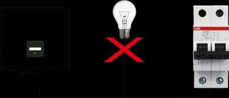
- Single-phase inverters cannot be used in three-phase combinations.
- Requires CT or Smart meter for export limitation function.
- USB port supports USB 2.0 only; do not use USB 3.0.

Manual page author
David Miller
Documentation analyst
Organizes user manual content into clear summaries, with attention to model details, product context, and everyday usability.