Hvac / Thermostats Controls
10GBASE-ZR SFP+ 1550nm 100km Industrial DOM Duplex LC Transceiver
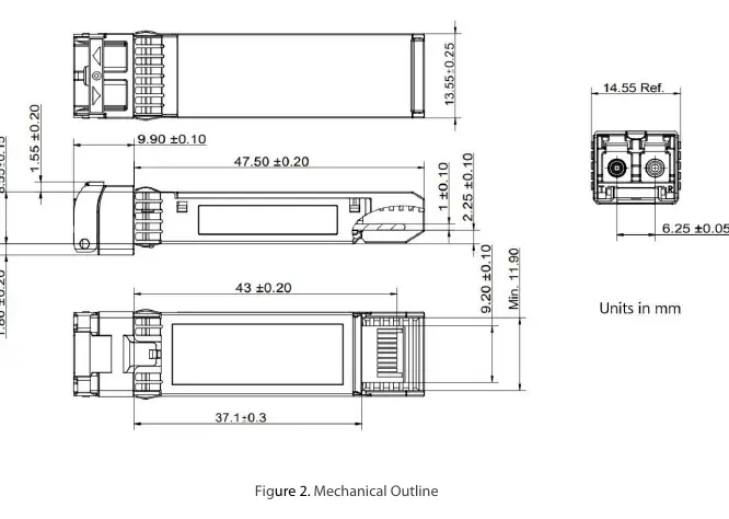
High-performance industrial-grade 10GBASE-ZR SFP+ optical transceiver designed for long-range data transmission up to 100km over single-mode fiber, featuring Digital Diagnostic Monitoring (DOM) and robust thermal tolerance.
Table of contents
Manual images
Jump to the sectionProduct Overview
The 10GBASE-ZR SFP+ Optical Transceiver is a high-performance module engineered for long-distance data transmission, supporting link lengths of up to 100km over single-mode fiber (SMF). This industrial-grade transceiver is fully compliant with SFP+ MSA and IEEE 802.3ae standards, ensuring seamless integration into existing network infrastructures. It is specifically designed to operate in harsh industrial environments, making it suitable for telecommunications, factory automation, intelligent transportation systems, and mining operations.
Key Features and Performance
This module utilizes a 1550nm EML transmitter and an APD receiver to achieve data rates up to 11.3Gb/s. It features a hot-pluggable SFP+ footprint, allowing for easy installation and maintenance without disrupting network operations. The device includes a Digital Diagnostic Monitoring (DOM) interface, accessible via a 2-wire serial interface as specified in SFF-8472, providing real-time monitoring of critical parameters such as temperature, supply voltage, and optical power levels.
Operational Reliability
Built for durability, the transceiver operates within an industrial temperature range of -40°C to 85°C. It is housed in a metal enclosure to minimize electromagnetic interference (EMI) and meets stringent ESD requirements, resisting up to 8KV direct contact voltage. The module requires a single 3.3V power supply and maintains a low power dissipation of less than 2W, ensuring energy efficiency in dense network deployments.
Installation and Safety
The transceiver uses a duplex LC/UPC optical interface for reliable fiber connections. Users should ensure that the host device is compatible with SFP+ MSA standards. During installation, handle the module with care to avoid damaging the optical interface. The device is classified as a Class 1 laser product per FDA/CDRH and IEC-825-1 regulations. Always ensure the fiber connectors are clean before insertion to maintain optimal signal integrity and prevent damage to the optical components.
Digital Diagnostics
The integrated DMI functionality allows for proactive network management. By monitoring the bias current, transmit/receive power, and internal temperature, administrators can identify potential link degradation before failure occurs. The module supports internal calibration, ensuring accurate reporting of diagnostic data across the entire operating range.
Manufacturer information
FS.com
Practical help
Common problems
Transmitter Fault (TFAULT)
Check if the TX bias current or output power exceeds preset alarm thresholds. Ensure the module is properly seated.
Loss of Signal (LOS)
Verify fiber connection integrity and cleanliness. Ensure the received optical power is within the specified sensitivity range (-25 dBm).
Module not detected
Ensure the module is fully inserted and the host device supports the SFP+ MSA standard. Check the MOD_ABS pin status.
Before use
- Verify the host device supports 10GBASE-ZR SFP+ modules.
- Clean the fiber optic connectors using an approved cleaning tool.
- Ensure the operating environment temperature is within -40°C to 85°C.
- Confirm the power supply is stable at 3.3V.
- Check that the fiber cable is single-mode (9/125µm).
- Inspect the SFP+ port for any physical obstructions or debris.
Specs in practice
- APD Receiver
- Avalanche Photodiode, highly sensitive receiver for long-range signals.
- Power Dissipation < 2W
- Maximum power consumption, ensuring low heat generation.
- Industrial Temp
- Designed to function reliably between -40°C and 85°C.
Images and diagrams
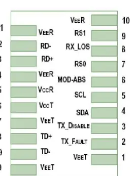
- The pinout diagram shows the 20-pin host board connector.
- Pins 1, 10, 11, 14, 17, 20 are ground connections.
- Pins 12/13 are for differential data output (RD-/RD+).
- Pins 18/19 are for differential data input (TD+/TD-).
- Pins 4/5 provide the 2-wire serial interface (SDA/SCL) for DOM.
Model compatibility
- Compliant with SFP+ MSA and IEEE 802.3ae standards.
- Tested for compatibility with major vendors including Cisco, Brocade, Dell, and Huawei.
- Requires 9/125µm single-mode fiber for 100km reach.

Manual page author
Michael Turner
Technical manual editor
Reviews PDF manuals for structure, safety notes, and practical product details so readers can find the right information quickly.