Garden / Fencing & Gates
Installation Manual for G21 Post 15x190 cm
Quick installation guide for the G21 15x190 cm gate post. Includes parts list, required tools, safety precautions, and step-by-step assembly instructions.
Table of contents
Manual images
Click an image to enlargeQuick guide from the manual
This document provides instructions for the assembly and installation of the G21 gate post (15x190 cm). Before starting, ensure you have all necessary parts and tools. Always prioritize safety by wearing protective gear and keeping the work area clear of children and pets.
Safety instructions
- Protective gear: Wear protective clothing and gloves during assembly, as some components may have sharp edges.
- Work area: Ensure that no children or pets are present in the working area during the assembly process.
Tools required
You will need the following tools for assembly:
- Hammer
- Drill (with 10mm bit)
- Tape measure
- Ladder
- Wrench (11mm)
- Protective gloves
Parts list
Verify that you have all the following components before beginning:
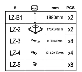
- LZ-B1: Post (x2)
- LZ-2: Cap (x2)
- LZ-3: Bolt M10x60mm (x8)
- LZ-4: Screw ST4.2x13mm (x4)
- LZ-5: Nut (x8)
Assembly instructions
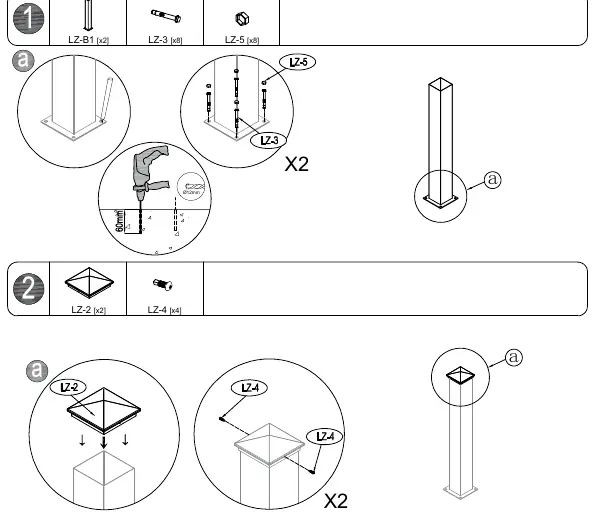
- Post installation: Secure the post (LZ-B1) to the ground using the provided bolts (LZ-3) and nuts (LZ-5). Use a drill to prepare the mounting points if necessary.
- Cap installation: Attach the cap (LZ-2) to the top of the post using the screws (LZ-4).
Care and maintenance
To maintain the condition of the post, clean it periodically using a rag and water.
Manufacturer information
G21
Practical help
Common problems
Sharp edges on components
Wear protective gloves and clothing during the entire assembly process.
Unsafe working environment
Ensure children and pets are kept away from the assembly area while working.
Before use
- Check that all parts listed in the parts list are present.
- Ensure you have all required tools (drill, hammer, wrench, etc.) ready.
- Wear protective clothing and gloves.
- Clear the work area of children and pets.
Specs in practice
- LZ-3 (M10x60mm)
- Bolts used for securing the post base.
- LZ-4 (ST4.2x13mm)
- Screws used for attaching the post cap.
Images and diagrams
- The parts list diagram identifies each component (LZ-B1 through LZ-5) with its corresponding quantity and dimensions.
- The assembly diagram illustrates the drilling process and the sequence for fastening the post and the cap.

Manual page author
Michael Turner
Technical manual editor
Reviews PDF manuals for structure, safety notes, and practical product details so readers can find the right information quickly.