Computers / Cooling Systems
User Manual for Gamemax RGB SMART 1300W Power Supply
Quick guide for the Gamemax RGB SMART 1300W power supply. Includes installation steps, connector descriptions, cable configuration, and technical specifications.
Table of contents
Manual images
Click an image to enlargeQuick Guide
The Gamemax RGB SMART 1300W is a fully modular power supply unit. Before installation, ensure the power supply I/O switch is in the off position and the AC power cord is disconnected. Use only the original modular cables provided with the unit to prevent damage to your PC components.
Safety and Warnings
- Do not disassemble the power supply.
- Use only original Gamemax modular cables. Using incompatible cables can cause damage to your system.
- Keep the power supply away from heat sources.
- Ensure proper ventilation for the PC case.
- Do not overload the power supply.
- It is recommended to reserve 15-20% of the power margin for the total system power consumption.
Installation Steps
Follow these steps to install the power supply:
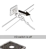
- Preparation: Ensure the I/O switch is off and the power cable is unplugged.
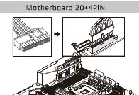
- Motherboard: Connect the 20+4 pin connector to the motherboard. Do not force the detachable 4-pin connector into an ATX12V 4-pin socket.
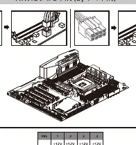
- CPU: Connect the ATX12V 4/8-pin (via 4+4 pin) connector to the motherboard.
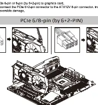
- Graphics Card (PCIe): Connect the PCIe 6-pin or 8-pin (via 6+2 pin) connector to the graphics card.
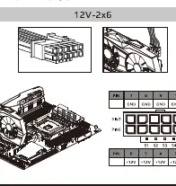
- Graphics Card (12V-2x6): Connect the 12V-2x6 (PCIe 5.0/5.1) cable to the graphics card. Ensure the cable is not bent vertically or horizontally within 35mm of the connector.
- Peripherals: Connect SATA cables to devices like HDD, SSD, or ODD. Connect PATA (Molex) cables to devices like fans or older drives.
- RGB Sync: Connect the 5V 3-pin ARGB connector to the motherboard's 5V 3-pin ADD header or a compatible HUB AURA SYNC header.
RGB Control
The unit features a manual RGB switch. Press the switch for 3 seconds to turn the light off. The unit includes a memory function to retain the last selected mode.
Specifications
AC Input: 100-240V, 15-8A, 47-63Hz.
DC Output:
- +3.3V: 20A
- +5V: 20A
- +12V: 108A
- -12V: 0.5A
- +5VSB: 2.5A
Max Combined Power: 1300W.
Cable Configuration
The unit is fully modular. Always verify the cable type before connecting. The package includes 20+4 pin motherboard cables, 4+4 pin CPU cables, 6+2 pin PCIe cables, 12V-2x6 cables, SATA cables, PATA cables, and an ARGB sync cable.
Practical help
Common problems
Incompatibility or system damage
Use only original Gamemax modular cables. Do not use cables from other power supplies.
Connector mismatch
Do not force the detachable 4-pin connector from the 20+4 pin cable into an ATX12V 4-pin socket.
Cable damage on 12V-2x6 connector
Do not bend the cable vertically or horizontally within 35mm of the connector.
Before use
- Ensure the I/O switch is in the OFF position.
- Unplug the AC power cord from the wall outlet.
- Verify that all components are compatible with the power supply.
- Ensure you have the correct modular cables for your specific devices.
- Check that the PC case has adequate ventilation.
Specs in practice
- DC Output +12V
- The primary rail for high-power components like CPU and GPU, supporting up to 108A.
Images and diagrams
- Motherboard 20+4PIN connector layout.
- ATX12V 4/8-pin CPU connector configuration.
- PCIe 6/8-pin and 12V-2x6 GPU connector layout.
- SATA and PATA/Molex peripheral connector pinouts.
Model compatibility
- Compatible with PCIe 5.0/5.1 graphics cards.
- Supports motherboard ARGB sync via 5V 3-pin header.

Manual page author
Michael Turner
Technical manual editor
Reviews PDF manuals for structure, safety notes, and practical product details so readers can find the right information quickly.