Power / Uninterruptible Power Supplies
User Manual for Milleteknik ECO Power Supply
Comprehensive user manual for the Milleteknik ECO series power supply and battery backup. Includes installation instructions, wiring diagrams, battery connection steps, LED alarm status, and troubleshooting guide.
Table of contents
Manual images
Click an image to enlargeQuick guide from the manual
The Milleteknik ECO series is a range of battery backups designed for access and locking systems. This document provides essential instructions for installation, battery connection, and system commissioning. Always ensure installation is performed by a competent electrician in accordance with national electrical rules.
Installation
The unit is intended for indoor installation on a wall or in a 19-inch rack. Ensure the environment is between 15°C and 30°C and free from high humidity or dust.
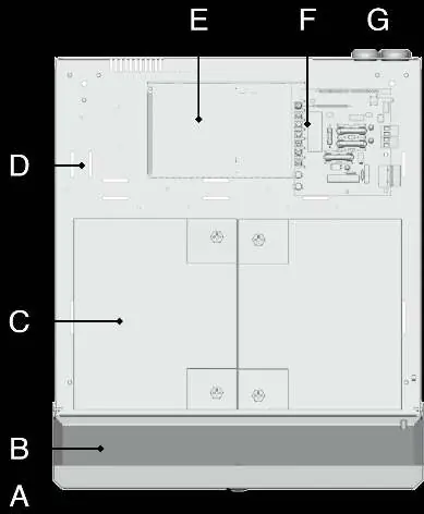
- Mounting: Mount vertically on a stable surface. Provide at least 100 mm of free space above and on the sides for ventilation.
- Electrical Requirements: The product is protection class I and must be connected to a grounded 230 V AC circuit.
- Main Switch: A main switch according to IEC 60947-1 must be included in the fixed installation and be easily accessible.
- Cabling: Use a supply cable with a cross-sectional area of at least 1.0 mm². Fit with a T 2.5 A (slow-blown) fuse or equivalent. Keep AC and low voltage cables separate to avoid interference.
Batteries - placement and connection
Caution: Before installation, measure the voltage of each individual battery. Never connect two batteries if their terminal voltage differs by more than 0.3 V (max 0.4 V) to prevent overheating or fire risk.
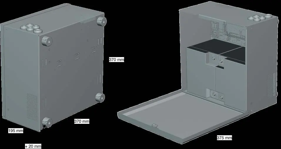
- Slide batteries into the enclosure from the side.
- Connect fuses to the batteries.
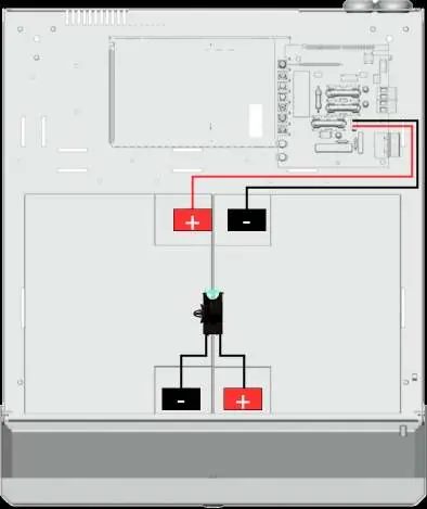
- Connect the red cable to the positive (+) terminal and the black cable to the negative (-) terminal.
- Connect the cables from the battery backup to the batteries, ensuring correct polarity.
Mains connection
Pull wiring through the cable entry on the cabinet. Connect the mains cable to the terminal on the motherboard (PCB). Ensure the marking on the circuit board matches the cable arrangement. Secure F (Phase) and N (Neutral) with cable ties for electrical safety.
Commissioning - how to start the unit
To minimize the risk of short circuits, connections to the motherboard must be made in the specified order. Ensure all cables are properly secured and grounded before energizing the unit. It may take up to 72 hours for batteries to be fully charged.
Alarm displayed on cabinet door
The indicator LED on the cabinet door provides status information:
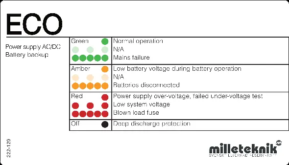
- Solid Green: Normal operation.
- Amber: Low battery voltage during battery operation or batteries disconnected.
- Red: Power supply over-voltage, failed under-voltage test, low system voltage, or blown load fuse.
- Off: Deep discharge protection is active.
Maintenance and Troubleshooting
The system is maintenance-free, except for the fan and batteries. If the device does not work as expected, check the following:
- No output voltage: Check mains voltage, fuses, and battery connections.
- Battery does not charge: Check battery cables and replace the battery fuse if necessary.
- Device starts but alarms: Ensure batteries are sufficiently charged (wait 72 hours) and the load does not exceed the rated current.
- Fuses blow frequently: Check for short circuits or overload.
- Device gets hot: Check for high load or insufficient ventilation.
Practical help
Common problems
No output voltage
Check mains voltage, fuses, and battery connections.
Battery does not charge
Check battery cables and replace the battery fuse if necessary.
Device starts but alarms
Wait 72 hours for batteries to charge. Ensure connected load does not exceed rated current.
Fuses blow frequently
Check for short circuit or overload. Replace fuse only after the cause is fixed.
Device gets hot
Check that rated current is not exceeded and ensure air flow around the housing.
Before use
- Ensure installation is performed by a competent electrician.
- Verify the unit is installed indoors in a 15-30°C environment.
- Check that the 230V AC circuit is grounded.
- Measure battery voltage before connection (max 0.3V difference).
- Ensure 100mm free space for ventilation.
- Disconnect mains voltage before starting installation.
Specs in practice
- Protection Class
- Class I (must be connected to a grounded circuit).
- Operating Temperature
- 15 - 30°C.
- Cable Area (230V)
- At least 1.0 mm².
Images and diagrams
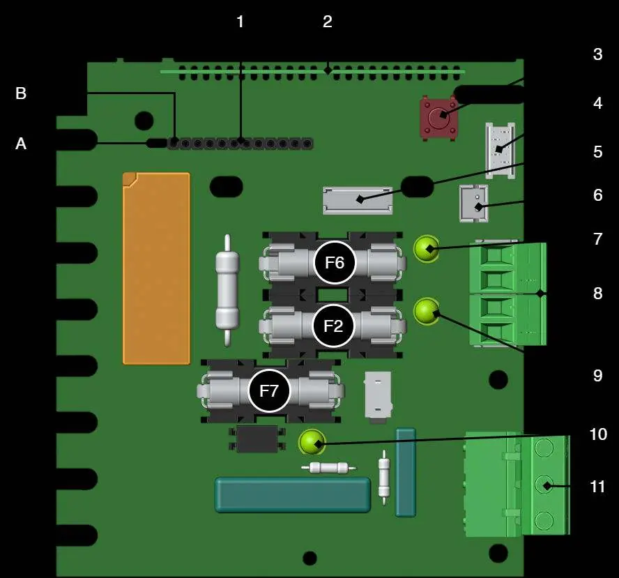
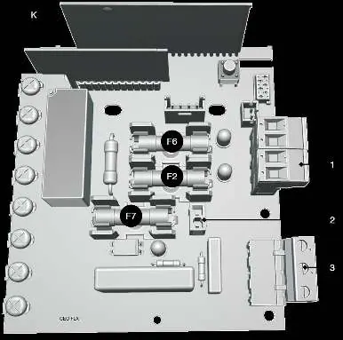
- Figure 1: Component overview of the motherboard.
- Figure 2: Battery connection diagram showing red/black cable routing.
- Figure 3: Mains connection to the motherboard terminal block.
- LED Status Panel: Explains the meaning of green, amber, and red light indicators.
Model compatibility
- Intended for indoor installation.
- Can be mounted on a wall or in a 19-inch rack.

Manual page author
Michael Turner
Technical manual editor
Reviews PDF manuals for structure, safety notes, and practical product details so readers can find the right information quickly.