Power / Transformers & Supplies
User Manual for Gamdias HELIOS P2-1300G Power Supply
Quick installation guide for the Gamdias HELIOS P2-1300G power supply. Includes step-by-step mounting instructions, cable connection diagrams, and technical specifications.
Table of contents
Manual images
Click an image to enlargeQuick Guide
This guide provides instructions for installing the Gamdias HELIOS P2-1300G power supply unit (PSU). Before beginning, ensure your PC case has sufficient space and that you have identified all necessary cables. Always turn off the PSU using the I/O switch (set to 'O') before performing any installation or cable connection tasks.
Package Contents
The package includes the following items:
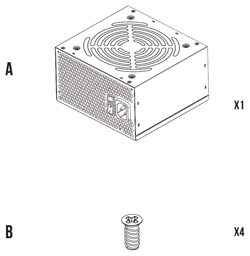
- HELIOS P2-1300G Power Supply Unit
- Mounting Screws (x4)
- Modular Cables: Motherboard Power Cable, CPU EPS Cables, GPU PCI-E Cables, 12VHPWR Cable, SATA Cables, Molex Cable, and FDD Cable.
Technical Specifications
The HELIOS P2-1300G is a high-efficiency power supply with the following output ratings:
- AC Input: 100-240V, 15-8A, 50-60Hz
- Total Power: 1300W
- DC Output: +3.3V (24A), +5V (24A), +12V (108.3A), -12V (0.5A), +5Vsb (3A)
Warning: The power supply must be powered by the source indicated on the rating label.
Connector Interface
The PSU features a fully modular design. The connector interface on the unit includes dedicated ports for:
- MB: Motherboard power
- CPU: Processor power
- PCI-E / 12VHPWR: Graphics card power
- SATA / Peripherals / IDE: Storage and accessory power
Installation Steps
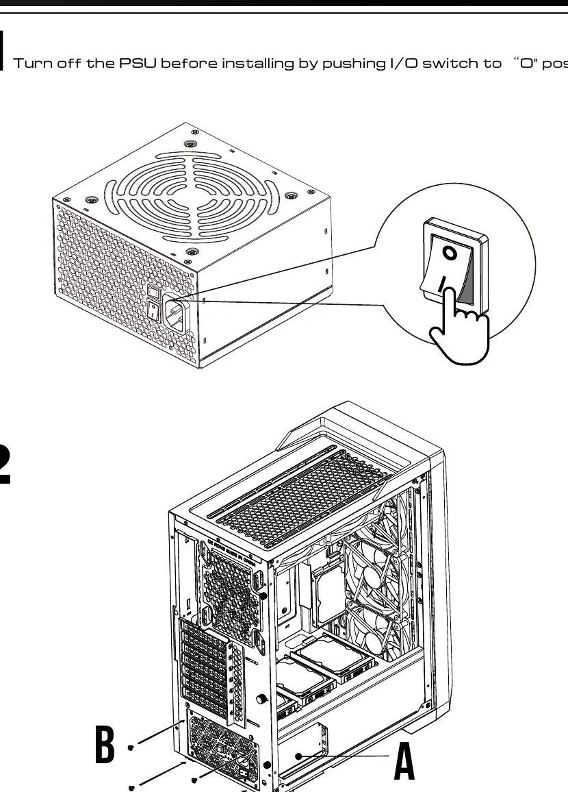
- Power Off: Ensure the PSU I/O switch is in the 'O' (Off) position before starting.
- Mounting: Install the PSU into your PC case using the provided screws.
- Motherboard: Connect the Motherboard Power Cable to the PSU and the motherboard.
- CPU: Connect the CPU EPS cable(s) to the PSU and the motherboard CPU power socket.
- GPU: Connect the PCI-E or 12VHPWR cable to the PSU and your graphics card.
- Storage/Peripherals: Connect SATA, Molex, or FDD cables as required by your components.
- Finalize: Plug the AC power cord into the wall outlet and the PSU.
- Power On: Push the I/O switch to the 'I' position to turn on the system.
Practical help
Common problems
System fails to power on
Ensure the I/O switch on the back of the PSU is set to the 'I' position and the AC power cord is firmly connected to both the wall outlet and the PSU.
Cable connection issues
Verify that you are using the correct modular cables provided with the unit. Do not force connectors into ports; they are keyed for specific orientations.
Before use
- Ensure the PSU I/O switch is set to 'O' (Off) before installation.
- Verify your PC case has adequate space for the PSU dimensions.
- Identify all necessary cables (Motherboard, CPU, PCIe, SATA) before starting.
- Ensure the AC power source matches the rating label (100-240V).
Images and diagrams
- Connector Interface: Shows the layout of modular ports on the PSU for connecting various system cables.
- Installation Steps: Visual guide for mounting the PSU and connecting cables to the motherboard, CPU, and GPU.
Model compatibility
- Compatible with standard ATX PC cases.
- Includes 12VHPWR cable for modern high-power graphics cards.

Manual page author
Michael Turner
Technical manual editor
Reviews PDF manuals for structure, safety notes, and practical product details so readers can find the right information quickly.