Smart Home / Smart Switches
GEWISS Chorusmart Connected Axial 2-Command Module User Guide
Quick guide for the GEWISS Chorusmart Connected Axial 2-Command Module (GWA1241, GWA1242). Includes installation, wiring, Zigbee setup, factory reset, and technical specifications.
Quick answers from the manual
Quick answer
- The GEWISS Chorusmart Connected Axial 2-Command Module is a Zigbee-enabled switch module for controlling lights, shutters, and scenes. It requires a 100-240V AC power supply and is configured via the Home Gateway App. p. 1
Key actions
- Pairing with Zigbee network p. 1
- Factory Reset p. 1
First start
- Download the Home Gateway App, ensure power is connected, and initiate pairing mode. p. 1
Problems and fixes
LED fixed red
Device not configured.
p. 1Maintenance and reset
- Press central local push-button for >10 seconds. p. 1
Technical specifications
| Parameter | Value | Meaning | Pages |
|---|---|---|---|
| Power supply | 100 – 240V AC, 50/60 Hz | Operating voltage | p. 1 |
Where to find it in the PDF
- Installation and Technical Data p. 1
Table of contents
Quick guide from the manual
The GEWISS Chorusmart Connected Axial 2-Command Module is a flush-mounting device designed to send two independent Zigbee commands. It is compatible with the EGO SMART plate. Key operations include wiring the device to the mains, pairing it with a Zigbee network via the Home Gateway App, and configuring the buttons for various functions like ON/OFF, dimming, or scene control.
Device description
The module features two independent front push-buttons and two auxiliary inputs. It acts as a Zigbee router, forwarding messages to other devices in the network. The device is designed to be completed with specific front button keys (diffuser or symbol lens types).
Installation and wiring
Attention: Always disconnect the mains voltage before installing or performing any work on the device.
- Ensure the device phase (L) is protected by a circuit breaker with a maximum rated current of 10A.
- Refer to the connection diagram (Fig. L) and Fig. D/H for terminal identification.
- Terminals are numbered 1-6: 1 (Not connected), 2 (Not connected), 3 (Auxiliary input 2), 4 (Auxiliary input 1), 5 (Power supply phase), 6 (Power supply neutral).
- To connect to the EGO SMART plate, insert the connection wire into the terminal block on the upper side of the device.
Programming and Zigbee setup
To program and use the device and the smart home system, download the Home Gateway app from the Play Store or App Store. To open the Zigbee network (Permit Join) and allow other devices to join, press the front push-button once. The front LED will turn green. Press again to close the network. The network will automatically close 15 minutes after opening.
Functions and operation
The front push-buttons can be configured for various functions, including ON/OFF/TOGGLE, timed ON (stair-light), curtain/roller shutter control, dimmer control, and scene execution. The auxiliary inputs can also be configured for these functions or to send sensor statuses. When mounted in an EGO SMART plate, the 'SHIFT' function can be enabled to manage a second set of commands.
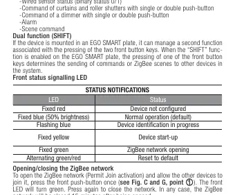
Status LED indicators
- Fixed red: Device not configured
- Fixed blue (50% brightness): Normal operation (default)
- Flashing blue: Device identification in progress
- Fixed yellow: Device start-up
- Fixed green: Zigbee network opening
- Alternating green/red: Reset to default
Factory reset
To reset the module and restore factory conditions, press and hold the central local push-button for more than 10 seconds.
Technical data
- Power supply: 100 – 240V AC, 50/60 Hz
- Radio connections: Zigbee (IEEE 802.15.4)
- Output power: Zigbee 10 dBm
- Transmission radius: External: 100 m in free field
- Operating temperature: -5°C to +45°C
- Degree of protection: IP20
Safety and disposal
The device must be used only for its intended purpose. Improper use may be dangerous. If the crossed-out bin symbol appears on the equipment or packaging, the product must be disposed of separately from general waste at the end of its life. Contact GEWISS Global Service & After Sales for support.
Practical help
Common problems
LED is fixed red
The device is not configured. Ensure it is paired with your Zigbee network.
Zigbee network not joining
Ensure the network is in 'Permit Join' mode by pressing the front button once (LED turns green).
Device not responding
Check power supply and ensure the circuit breaker is active.
Before use
- Disconnect mains voltage before installation.
- Verify the circuit breaker is rated max 10A.
- Download the Home Gateway App.
- Identify the correct terminal wiring (1-6).
- Ensure the device is installed in a dry indoor environment.
Specs in practice
- Zigbee (IEEE 802.15.4)
- The wireless communication protocol used for smart home connectivity.
Images and diagrams
- Fig. L: Wiring diagram showing connections for phase, neutral, and auxiliary inputs.
- Fig. D/H: Terminal block location for EGO SMART plate connection.
Model compatibility
- Requires EGO SMART plate for full functionality.
- Compatible with GWA1241 and GWA1242 modules.
- Requires specific front button keys (diffuser or symbol lens types).

Manual page author
David Miller
Documentation analyst
Organizes user manual content into clear summaries, with attention to model details, product context, and everyday usability.