Home Appliances / Space Heaters
Goldair Ceramic Wall Heater Installation Guide
Quick installation guide for the Goldair Ceramic Wall Heater. Includes essential mounting clearances, safety precautions, installation steps, and remote control usage.
Quick answers from the manual
Quick answer
- The Goldair Ceramic Wall Heater must be wall-mounted on a heat-resistant surface. It requires specific clearances: 1.8m from the floor, 300mm from the ceiling, 200mm from sides, and 300mm from the bottom. p. 1, 2
Key actions
- Install the heater p. 2
First start
- Ensure all packaging is removed and the unit is securely wall-mounted before operation. p. 1
Problems and fixes
Thermal safety device activation
Do not cover the heater or restrict airflow.
p. 1Maintenance and reset
- Do not turn off at the wall while the fan is running after the unit is turned off. p. 1
Technical specifications
| Parameter | Value | Meaning | Pages |
|---|---|---|---|
| Floor clearance | 1.8m | Minimum distance from floor | p. 1, 2 |
| Ceiling clearance | 300mm | Minimum distance from ceiling | p. 1, 2 |
Where to find it in the PDF
- Safety and Installation Requirements p. 1
- Installation Diagram and Steps p. 2
Table of contents
Quick guide from the manual
This document provides essential installation requirements and safety precautions for the Goldair Ceramic Wall Heater. The heater must be wall-mounted on a heat-resistant surface that complies with current building regulations. Ensure all packaging is removed before installation.
Installation Requirements
Proper clearance is critical for the safe operation of the heater. Adhere to the following minimum distances:
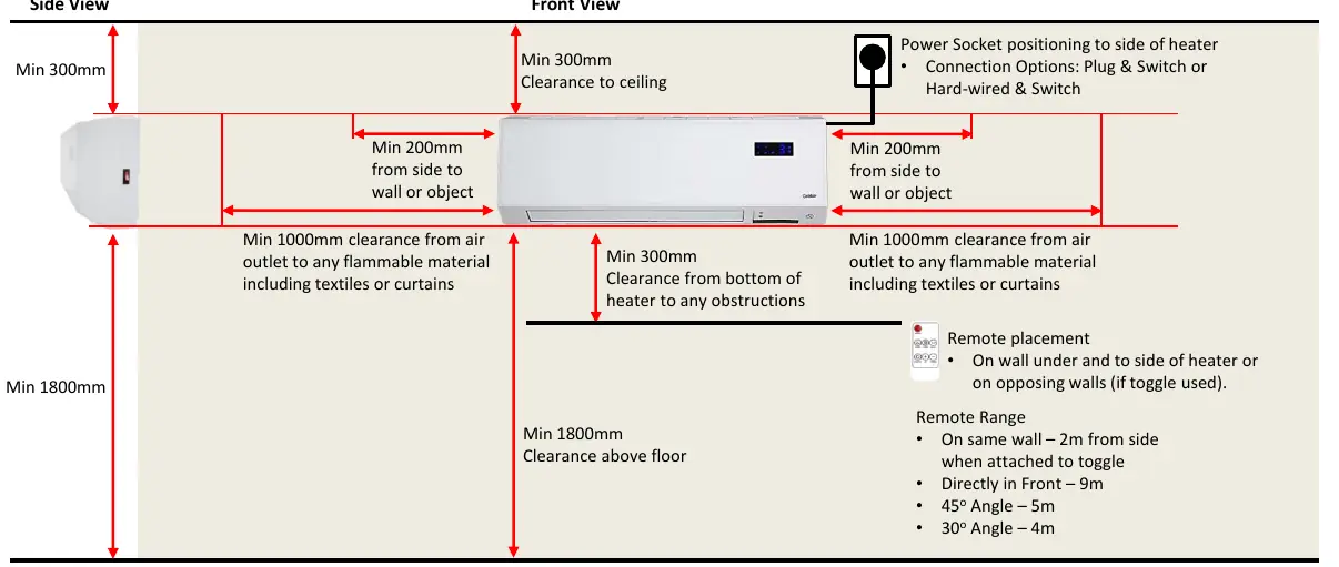
- Floor: 1.8m clearance.
- Ceiling: 300mm clearance.
- Sides: 200mm clearance from walls or objects.
- Bottom: 300mm clearance from any obstructions (shelves, pictures, etc.).
- Air Outlet: 1.0m clearance from any flammable materials, including textiles and curtains.
Important Safety Notes:
- Do not mount the heater directly under or above an electrical power socket. It is recommended to install the heater to the side of the socket.
- Do not mount the heater above a door.
- Do not run the power cord behind the heater.
- Never cover the heater or restrict its airflow, as this will trigger the thermal safety device.
Installation Steps
- Measure the distance between the mounting holes on the back of the appliance and mark the wall accordingly, ensuring the marks are level.
- Drill holes to match the diameter of the wall plugs.
- Insert the wall plugs and fix two screws into the wall, leaving the heads protruding approximately 10mm.
- Hang the heater on the screws, then slide it to the right and down to lock it into position.
Operation and Remote Control
When the unit is turned off, the fan will continue to run for a short period to protect internal components. Do not turn off the power at the wall during this cooling phase. The remote control can be placed to the side of the heater or on opposing walls. The remote range varies based on the angle: 9m directly in front, 5m at a 45-degree angle, and 4m at a 30-degree angle.
Manufacturer information
Goldair
Practical help
Common problems
Thermal safety device activation
Ensure the heater is not covered and airflow is not restricted.
Fan continues running after turn-off
This is normal operation to protect internal components. Do not turn off the power at the wall during this time.
Before use
- Remove all packaging from the unit.
- Verify the wall is heat-resistant and complies with building regulations.
- Check that the installation location is not directly above or below a power socket.
- Ensure the mounting surface is level.
- Confirm all clearance distances (floor, ceiling, sides, bottom) are met.
Specs in practice
- Floor clearance
- Minimum 1.8m distance from the floor.
- Ceiling clearance
- Minimum 300mm distance from the ceiling.
- Side clearance
- Minimum 200mm distance from walls or objects.
- Bottom clearance
- Minimum 300mm distance from obstructions.
Images and diagrams
- The installation diagram illustrates the required clearances from walls, ceiling, floor, and flammable objects.
- The diagram shows the correct positioning of the power socket to the side of the heater.
Model compatibility
- Must be wall-mounted.
- Mount only on heat-resistant walls complying with AS/NZS specifications.

Manual page author
Michael Turner
Technical manual editor
Reviews PDF manuals for structure, safety notes, and practical product details so readers can find the right information quickly.