Power / EV Chargers
Installation Guide for EcoFlow OCEAN EV Charger 11.5kW
A comprehensive installation and operation guide for the EcoFlow OCEAN EV Charger 11.5kW. This manual covers safety, installation steps, electrical wiring diagrams, LED status indicators, and charging instructions.
Table of contents
Manual images
Click an image to enlargeQuick Guide
The EcoFlow OCEAN EV Charger 11.5kW is designed for outdoor use and can operate in standalone mode or integrated with the EcoFlow OCEAN Pro Solar Battery System or EcoFlow OCEAN Smart Electrical Panel. Ensure all electrical connections are performed by a certified electrician. The device requires a dedicated circuit with a 60A AC breaker.
Safety Instructions
Before installation, operation, or maintenance, read the full manual. Personnel must be trained and possess necessary local qualifications for high-voltage operations. Always disconnect power before servicing and wear appropriate Personal Protective Equipment (PPE).
Installation
Environment Requirements: Install on a flat, vertical, fire-resistant surface in a well-ventilated area. Avoid direct solar radiation, flammable sources, and strong electromagnetic fields. The unit is weather-resistant but not designed for complete immersion.
Angle Requirements: Install vertically or with a maximum back tilt of 15 degrees to ensure proper heat dissipation.
Space Requirements: Maintain ample clearance around the unit. The storage means for the coupling device should be mounted between 600 mm (24 inches) and 1.2 m (48 inches) from the ground.
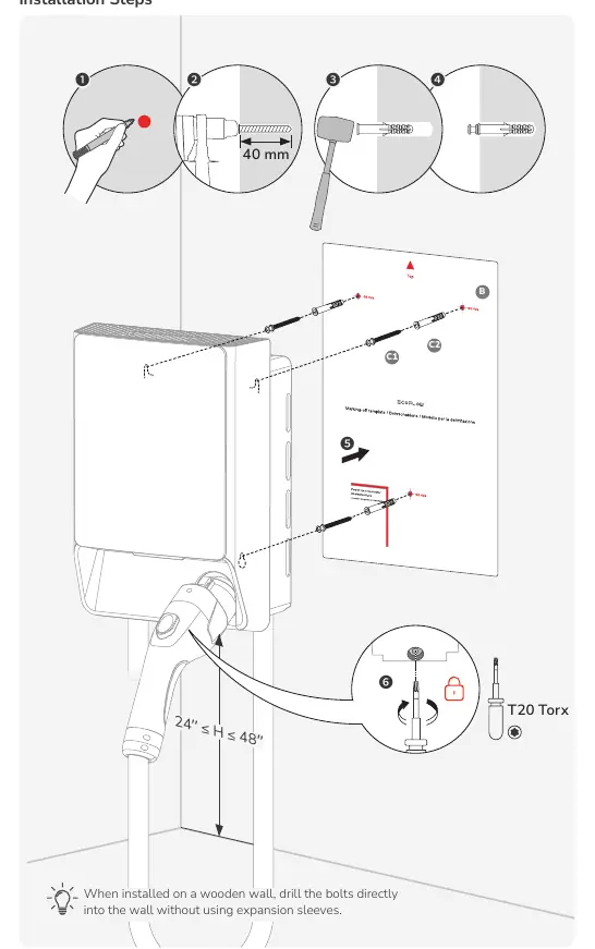
Installation Steps:
- Mark the drilling positions using the provided fixing template.
- Drill holes (40 mm depth) and insert wall plugs.
- Secure the charger to the wall using the provided installation kit.
- Tighten the screws using a T20 Torx screwdriver.
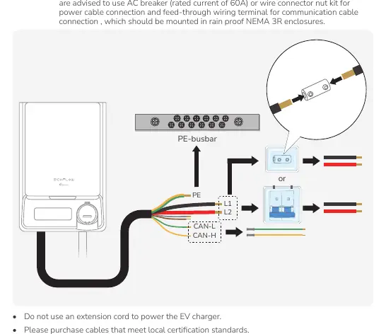
Electrical Connection
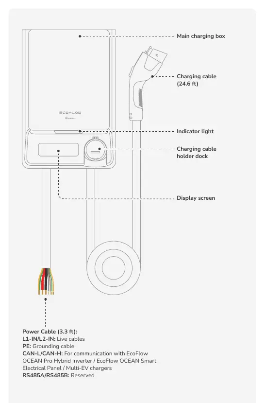
All connections must be carried out by a certified professional. Install a certified RCBO upstream close to the charging station. The power cable is 3.3 ft long and intended for hard-wiring. Use 6 AWG cables for L1, L2, and PE connections. For communication with external EcoFlow devices, use the CAN-H/CAN-L cables or Wi-Fi.
LED Indicators
The LED light provides status updates:
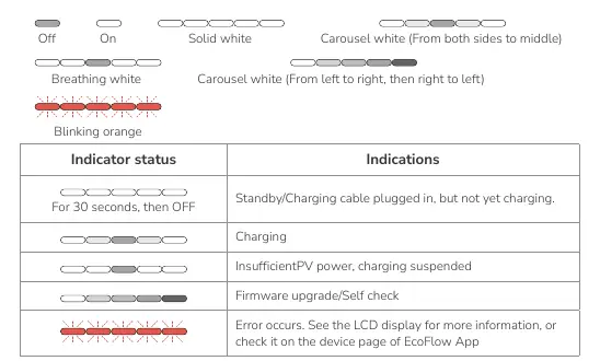
- Off: Standby/Charging cable plugged in, but not yet charging.
- Solid White: Charging.
- Carousel White (both sides to middle): Firmware upgrade or self-check.
- Blinking Orange: Error occurred. Check the LCD display or EcoFlow App for details.
LCD Display
The LCD screen displays real-time data including:
- Metering: Software version, total electricity consumption.
- Network: Wi-Fi and Bluetooth connection status.
- Power Supply: PV input, Grid power input, Battery input.
- Charging: Input current, input voltage, output power, EV SOC, and accumulated charging hours.
Charging Your EV
Method 1: Via EcoFlow App: Connect the charger to your vehicle, open the app, and initiate charging. Do not use unauthorized adapters or extensions.
Method 2: Plug and Play: Enable this function in the EcoFlow App Device Settings. Once enabled, simply plug the charger into your vehicle to start charging automatically.
Manufacturer information
EcoFlow
Practical help
Common problems
Charging suspended
Check if PV power is insufficient or if there is an error code on the LCD display.
Blinking orange LED
An error has occurred. Consult the LCD display for the error code or check the device page in the EcoFlow App.
Circuit breaker trips
Ensure the home electrical circuit can carry the operating current of the charger.
Before use
- Ensure the installation site is level, vibration-free, and free from contamination.
- Verify the mounting structure is fire-resistant.
- Confirm the AC circuit breaker (60A) is installed upstream.
- Ensure all cables are connected correctly before turning on the RCBO.
- Verify the installation height is between 600mm and 1.2m from the ground.
Images and diagrams
- Wiring Diagram: Illustrates connections for Standalone, Smart Electrical Panel, and Solar Battery System configurations.
- Installation Steps: Shows the sequence of marking, drilling, and securing the unit to the wall.
Model compatibility
- Compatible with EcoFlow OCEAN Pro Hybrid Inverter.
- Compatible with EcoFlow OCEAN Smart Electrical Panel.

Manual page author
David Miller
Documentation analyst
Organizes user manual content into clear summaries, with attention to model details, product context, and everyday usability.