Tools / Welding Equipment
User Manual for Güde MIG 192/6K Welding Machine
Quick guide for the Güde MIG 192/6K welding machine. Includes setup, operation, maintenance, and troubleshooting steps for optimal welding performance.
Table of contents
Manual images
Click an image to enlargeQuick guide from the manual
This manual provides essential information for the safe and efficient operation of the Güde MIG 192/6K welding machine. Before use, ensure you have read the full safety instructions, particularly regarding the duty cycle (ED%) and personal protective equipment. Always operate the machine in a dry environment and ensure proper grounding.
Product Overview
The MIG 192/6K is a gas-shielded welding machine (MAG) designed for workshop use. It is suitable for welding various metals, including steel, stainless steel, and copper. It features a step-up transformer, built-in wire feed, and adjustable voltage settings.
Installation and Assembly
- Assembly: Follow the instructions to mount the wheels, handle, gas bottle, and welding shield.
- Environment: Ensure the workspace is dry and well-ventilated. Avoid dusty or dirty areas.
- Grounding: Connect the grounding cable as close to the welding area as possible.
Operation
Wire Feed Installation: Open the side door, insert the wire spool, and ensure the wire is straight and free of burrs. Adjust the pulley pressure so the wire feeds evenly without slipping or being crushed.
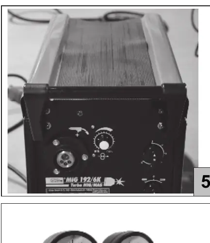
Voltage Selection: The machine supports 230V or 400V. Use the provided adapter for 230V or connect directly to a 400V CEE 16A outlet.
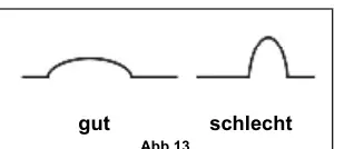
Welding: Set the voltage and wire feed speed according to the material thickness. Maintain a torch angle of approximately 30° to the workpiece. Always perform a test weld on scrap material first.
Maintenance
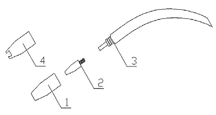
- Hose Set: Regularly clean the wire guide and gas nozzle. Use protective spray on the nozzle to prevent slag buildup.
- Current Nozzle: Check the wire hole diameter and replace if worn.
- Gas Distributor: Clean or replace if gas flow is obstructed.
Troubleshooting
- No Welding Current: Check thermal protection (wait 10 minutes for reset) or check fuses/RCD.
- Irregular Wire Feed: Clean the wire guide, check for clogged nozzles, or adjust pulley pressure.
- Porous Welds: Ensure gas supply is open, clean the material, and check the torch angle.
- Weak Penetration: Increase welding current and wire feed speed.
Practical help
Common problems
Welding current fails
Thermal protection may have triggered due to overload. Wait approximately 10 minutes for the transformer to cool down.
Irregular wire feed
Clean the wire guide with compressed air, check for clogged gas nozzles, or adjust the pulley pressure.
Porous welds
Check gas supply, clean the material surface, and ensure the torch is held at the correct 30° angle.
Weak penetration
Increase the welding current and wire feed speed, and keep the torch closer to the workpiece.
Before use
- Read the entire operating manual.
- Ensure the electrical connection is properly fused.
- Wear appropriate protective clothing (welding helmet, apron, gloves).
- Ensure the workspace is dry and well-ventilated.
- Check that the gas bottle is securely fixed and connected.
- Verify the wire diameter matches the pulley grooves.
Specs in practice
- ED% (Duty Cycle)
- The ratio of welding time to cooling time within a 10-minute cycle. For example, 60% ED means 6 minutes of welding followed by 4 minutes of cooling.
- Material Thickness
- Recommended range is 1-9 mm.
Images and diagrams
- Fig 11: Wire feed installation and pulley adjustment.
- Fig 13: Correct welding angle (approx. 30°) vs incorrect angle.
- Fig 15: Maintenance of the nozzle, current nozzle, and gas distributor.
Model compatibility
- Suitable for steel, stainless steel, and copper.
- Requires Co2/Argon mixed gas for MAG welding.
- Requires appropriate wire diameter (0.6-1.0 mm).

Manual page author
Emily Carter
User documentation editor
Prepares concise manual descriptions and highlights the most useful setup, operation, and maintenance information for readers.