Tools / Welding Equipment
User Manual for GYS Trimig Welding Units
Comprehensive user guide for GYS Trimig series welding units. Includes setup, synergic mode operation, maintenance, safety precautions, and troubleshooting.
Quick answers from the manual
Quick answer
- The GYS Trimig is a semi-automatic welding unit. To operate, connect to a 400V 3-phase supply, install the correct wire and gas, and select either Manual or Synergic mode on the control panel. p. 4, 5, 6
Key actions
- Adjusting wire speed in Manual mode p. 6
- Setting up Synergic mode p. 6
First start
- Initial setup of reel and rollers p. 5
Problems and fixes
Wire rubs down after rollers
Check covering wire guide, clean/replace torch, or reduce wire speed.
p. 8Maintenance and reset
- Cleaning dust p. 7
Technical specifications
| Parameter | Value | Meaning | Pages |
|---|---|---|---|
| Duty Cycle (Trimig 200-4S) | 200A @ 30% | Performance at 40°C | p. 6 |
Where to find it in the PDF
- Device Presentation p. 2, 4
- Operation and Settings p. 3, 5, 6
- Troubleshooting p. 8
Table of contents
Manual images
Click an image to enlargeQuick guide from the manual
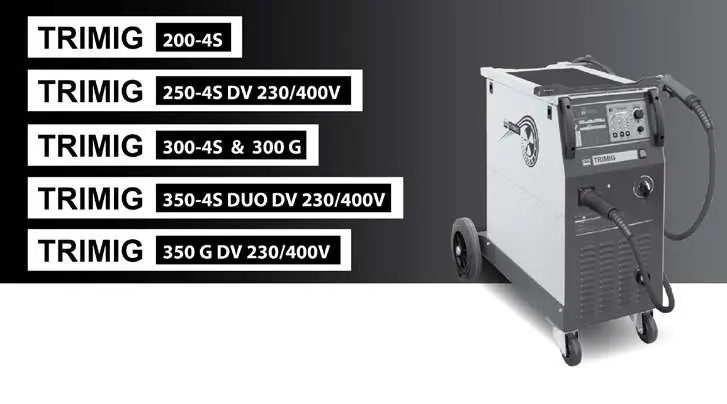
The GYS Trimig series are semi-automatic MIG/MAG welding units designed for industrial use. They require a 400V three-phase power supply (or 230V three-phase for DV models). Always ensure the power supply and circuit protection are compatible with the device requirements before use.
Device presentation
The unit features a control panel for selecting welding modes (Manual or Synergic), a torch connection, and a wire feeder system. The gas bottle support is located at the rear and must be secured with the provided chain.
Setup and installation
- Reel Assembly: Open the machine door, position the reel on the support, and adjust the reel brake to prevent tangling.
- Wire Feeder: Use the appropriate rollers for the wire diameter (0.8/1.0 or 1.0/1.2). Ensure the visible diameter on the roller matches the wire in use.
- Gas Coupling: Connect the regulator/flowmeter to the gas bottle and attach the gas pipe to the connector using the provided collars.
Welding modes
Manual mode
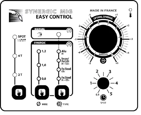
In manual mode, the user sets the welding voltage using the two power switches and adjusts the wire speed manually using the potentiometer.
Synergic mode
This mode automatically controls wire speed. Set the wire speed potentiometer to the 'OPTIMAL SYNERGIC' zone and select the wire type, diameter, and power setting. The device determines the optimum speed based on these parameters.
Maintenance
- Cleaning: Remove the steel cover 2-3 times a year to remove dust.
- Cables: Regularly check the condition of the power supply cord and welding cables.
- Ventilation: Ensure ventilation holes are never blocked to allow proper cooling.
Safety
Arc welding is dangerous. Always wear protective clothing, gloves, and a helmet with appropriate filters (EN169 or EN379). Work in a well-ventilated area and keep flammable materials away. People with pacemakers should consult a doctor before using this device.
Manufacturer information
GYS
Practical help
Common problems
Welding wire speed is not constant
Clean the contact tip, check roller pressure, or replace the wire guide.
Unwinding motor does not operate
Release the brake on the reel or rollers, and check that the power switch is in the ON position.
No welding current
Check the main supply connection, ensure the plug is fed by 3 phases, and inspect the earth connection.
Porous welding cord
Increase gas flow (15-20 L/min), replace empty gas bottle, or clean the working metal.
Before use
- Verify power supply and protection (fuse/breaker) are compatible.
- Ensure the gas bottle is securely fastened with the chain.
- Check that the correct contact tip and roller diameter are installed for the wire type.
- Ensure ventilation holes are not blocked.
- Inspect welding cables and earth clamp for damage.
Specs in practice
- Synergic Mode
- Automatic wire speed adjustment based on voltage, wire diameter, and power mode.
Images and diagrams
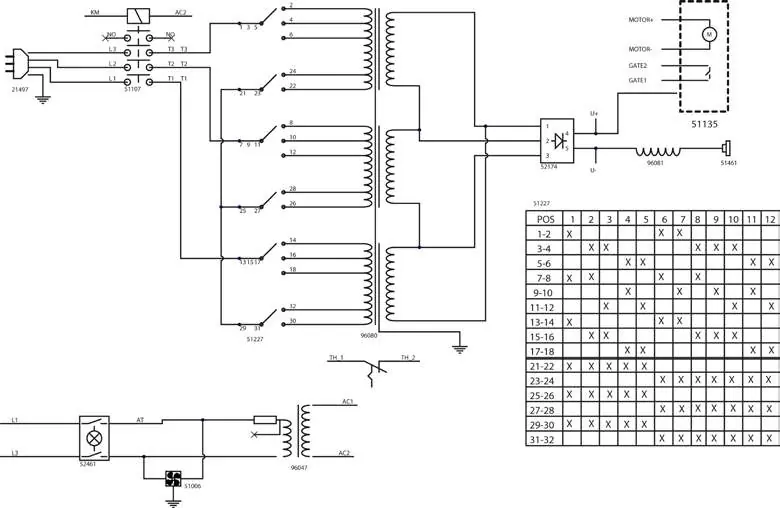
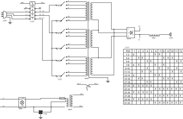
- Fig II: Device components including torch connection, earth cable, and reel support.
- Fig V: Control panel layout for manual and synergic welding modes.
- Fig VI: Synergic mode settings table for wire diameter and material thickness.
Model compatibility
- Requires 400V three-phase power supply (230V three-phase for DV models).
- Compatible with steel, stainless steel, and aluminium wires.
- Requires specific gas (Argon + CO2 for steel, pure Argon for aluminium).

Manual page author
Emily Carter
User documentation editor
Prepares concise manual descriptions and highlights the most useful setup, operation, and maintenance information for readers.