Garden / Portable Garages
User Manual for Central Pneumatic 1/4-Inch Air Hydraulic Riveter
Quick guide for the Central Pneumatic 1/4-Inch Air Hydraulic Riveter (Item 62685). Includes setup, operation, maintenance, jaw replacement, and troubleshooting steps.
Table of contents
Manual images
Click an image to enlargeQuick guide from the manual
This manual provides instructions for the Central Pneumatic 1/4-Inch Air Hydraulic Riveter (Item 62685). Before use, ensure the work area is clean and well-lit. Always wear ANSI-approved eye protection, hearing protection, and a dust mask. Do not exceed the maximum air pressure of 120 PSI. Ensure the air supply is clean, dry, and regulated.

Components and Controls
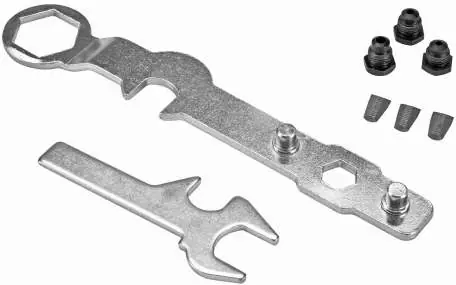
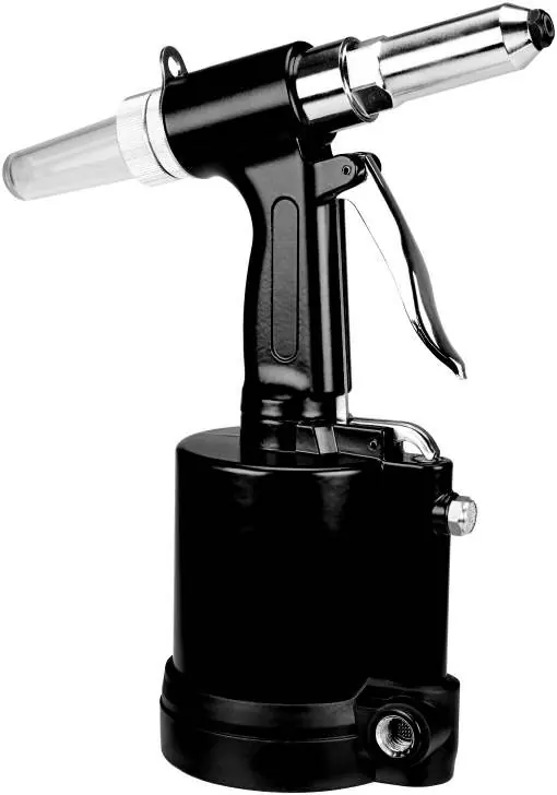
The riveter features a trigger, air inlet, pin cap, and interchangeable nosepieces. The kit includes a wrench and wrench gauge for maintenance and jaw adjustments. The riveter supports 1/8", 5/32", 3/16", and 1/4" rivets, requiring a nosepiece change for each size.
Setup and Air Supply
To set up the air supply, incorporate a filter, regulator, and in-line shutoff valve. Do not install a female quick coupler directly on the tool to prevent accidental operation. If an automatic oiler is not used, add a few drops of pneumatic tool oil to the airline connection before use and after each hour of operation.
Priming the Cylinder
If the tool requires priming:
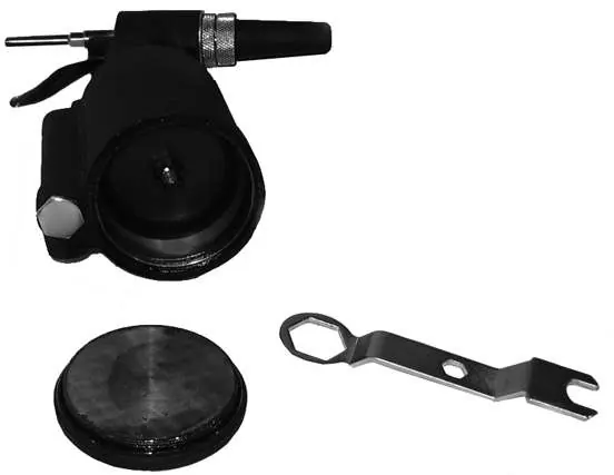
- Remove the base cover and unscrew the air cylinder cap.
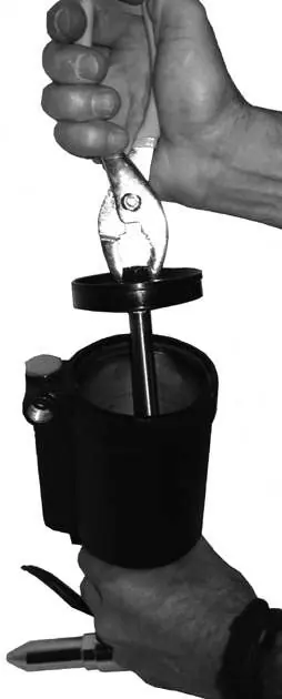
- Use pliers to remove the piston head.
- Pour hydraulic fluid into the air cylinder until it reaches the top of the housing.
- Reinsert the piston head and screw the air cylinder cap back on.
Operation
- Attach the correct nosepiece for the rivet size using the included wrench.
- Connect the air hose to the air inlet.
- Insert the rivet through the nosepiece.
- Place the rivet into the predrilled hole in the workpiece.
- Hold the riveter firmly against the workpiece and squeeze the trigger to activate.
- Release the trigger after the rivet is set.
Maintenance and Cleaning
Inspect the tool before each use for loose hardware, binding parts, or damage. Perform daily air supply maintenance by draining the moisture filter and checking the lubricator oil level. Every 3 months, have the internal mechanism cleaned and lubricated by a qualified technician.
Jaw Cleaning and Replacement
- Unscrew the outer cylinder and jaw case.
- Remove the jaws from the jaw case.
- Clean the jaws with a steel brush and mild solvent, then apply a light coat of machine oil.
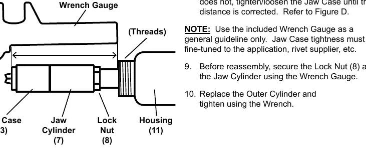
- Reassemble the jaw case, ensuring the wedge on the jaw pusher is aligned between the jaws.
- Use the wrench gauge to check the distance from the jaw case head to the housing threads to ensure proper tightness.
Troubleshooting
If the tool is not performing correctly, check the following:
- Jaws slipping: Replace worn or damaged jaws.
- Jaws will not open: Tighten the nosepiece or clean the jaws.
- Stroke too short: Ensure the rivet pin is fully inserted, prime the riveter, or use the correct rivet length.
- Weak pulling action: Check the air regulator, service the compressor, or prime the riveter.
- Leaking air: Reconnect using pipe thread seal tape, replace O-rings, or clean the air valve.
Manufacturer information
Harbor Freight Tools
Practical help
Common problems
Jaws slipping
Replace worn or damaged jaws.
Jaws will not open
Tighten the nosepiece or clean the jaws.
Stroke is too short
Fully insert the rivet pin, prime the riveter, or use the proper rivet length.
Weak pulling action
Check the air regulator, service the compressor, or prime the riveter.
Leaking air
Reconnect using pipe thread seal tape, replace O-rings, or clean the air valve.
Before use
- Inspect the tool for damaged, loose, or missing parts.
- Ensure the air supply is clean, dry, and regulated (max 120 PSI).
- Install an in-line shutoff valve for emergency control.
- Attach the correct nosepiece for the rivet size.
- Ensure the Pin Cap is secure and the slot is turned upward.
- Add a few drops of pneumatic tool oil to the air inlet if no automatic oiler is used.
Specs in practice
- Maximum Air Pressure
- 120 PSI. Do not exceed this to prevent tool failure or injury.
- Average Air Consumption
- 4.5 CFM at 90 PSI.
- Rivet Pin Capacity
- Supports 1/8", 5/32", 3/16", and 1/4" rivets (requires nosepiece change).
Images and diagrams
- Figure A/B: Shows the recommended air supply setup including filter, regulator, and lubricator.
- Figure C: Illustrates the priming process for the air cylinder.
- Figure D: Shows how to use the Wrench Gauge to check jaw case tightness.
Model compatibility
- Requires nosepiece change for different rivet sizes.
- Do not use oxygen, carbon dioxide, or combustible gases as an air source.
- Use only identical replacement parts for service.

Manual page author
Emily Carter
User documentation editor
Prepares concise manual descriptions and highlights the most useful setup, operation, and maintenance information for readers.