Tools / Power Tools
User Manual for HiKOKI G 18BYE Disc Grinder
Quick guide for the HiKOKI G 18BYE Disc Grinder. Includes safety instructions, mounting procedures for wheels and guards, operation tips, maintenance, and troubleshooting via notification lamp codes.
Table of contents
Manual images
Click an image to enlargeQuick guide from the manual
This manual provides essential safety and operational instructions for the HiKOKI G 18BYE Disc Grinder. Always read the full safety warnings before use. The tool features a notification lamp to indicate status: a steady green light means standby, a steady red light indicates the restart protection function is active, and a blinking red light indicates overload or overheating protection has been triggered.
Product overview and applications
The G 18BYE is designed for:
- Removing casting fins and finishing various steel, bronze, and aluminum materials.
- Grinding welded sections or sections cut by a torch.
- Grinding synthetic resins, slate, brick, and marble.
- Cutting synthetic concrete, stone, brick, and marble.
Specifications
- Model: G 18BYE
- Power Input: 1950W
- Rated Speed: 6600/min
- Wheel Diameter: 180mm
- Hole Diameter: 22.23mm
- Weight: 4.0kg
Mounting and operation
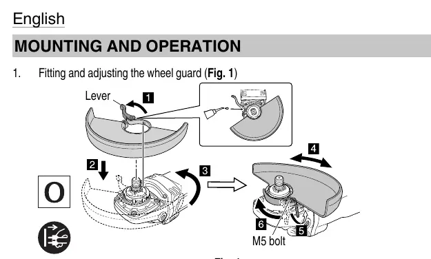
Wheel Guard: Ensure the wheel guard is fitted and adjusted correctly using the lever and M5 bolt before operation.
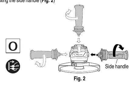
Side Handle: Securely fix the side handle to the tool body for better control.
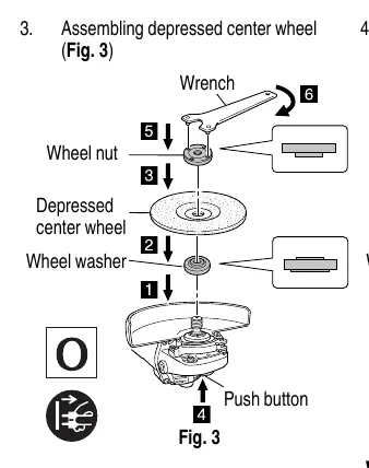
Wheel Assembly: Use the included wrench to tighten the wheel nut. Ensure the wheel washer is correctly positioned. Always confirm the spindle lock is disengaged by pushing the button two or three times before switching the tool on.
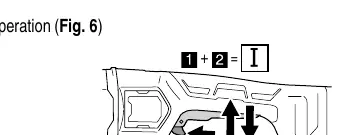
Switch Operation: The tool features a trigger switch. Ensure the switch is in the OFF position before connecting to power.
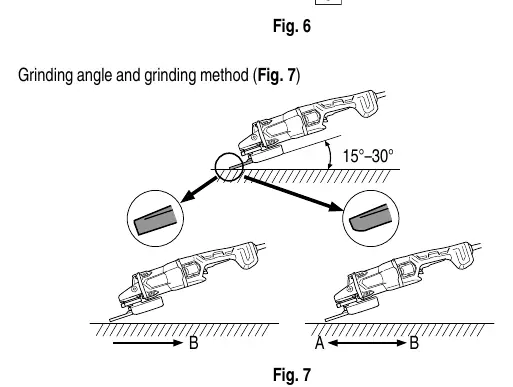
Grinding Method: Maintain a grinding angle of 15°–30° for optimal results.
Maintenance and inspection
Regularly inspect the grinding wheel for cracks or defects. Check all mounting screws periodically and tighten if loose. The motor is the heart of the tool; keep it clean by blowing air through the tail cover air hole while the motor is running without load. If the power cord requires replacement, it must be performed by a HiKOKI Authorized Service Center.
Manufacturer information
HiKOKI
Practical help
Common problems
Tool stops due to overload
Release the switch, remove the cause of the overload, and then restart.
Tool stops due to overheating
Disconnect the power plug and allow the unit to cool in a well-ventilated, shaded area.
Brake kickback
Hold the main body securely when releasing the switch, as the electric brake may cause some kickback.
Before use
- Check that the power source matches the product nameplate.
- Ensure the switch is in the OFF position before plugging in.
- Inspect the grinding wheel for cracks or surface defects.
- Ensure the wheel guard is securely attached.
- Confirm the spindle lock is disengaged.
- Use a residual current device (RCD) with a rated current of 30mA or less.
Specs in practice
- Wheel diameter
- 180mm
Images and diagrams
- Fig 1: Wheel guard installation and adjustment.
- Fig 2: Side handle installation.
- Fig 3-5: Assembly steps for different wheel types (depressed center, cutting, diamond).
- Fig 6: Switch operation (I/O).
- Fig 7: Recommended grinding angle (15-30 degrees).
Model compatibility
- Use only recommended wheel types.
- Do not use cutting-off wheels for side grinding.
- Do not use separate reducing bushings or adapters for large hole wheels.

Manual page author
Emily Carter
User documentation editor
Prepares concise manual descriptions and highlights the most useful setup, operation, and maintenance information for readers.