Tools / Drills
User Manual for HiKOKI D 10VC3 Drill
Quick guide for the HiKOKI D 10VC3 drill. Includes safety warnings, drilling instructions, maintenance, specifications, and operation steps.
Table of contents
Manual images
Click an image to enlargeQuick guide from the manual
This manual provides essential information for the safe and efficient operation of the HiKOKI D 10VC3 drill. Always read the safety warnings before use.
Safety Warnings
Follow all general power tool safety warnings, including keeping the work area clean, using personal protective equipment (eye protection), and avoiding unintentional starting. Drill-specific warnings include using auxiliary handles, holding the tool by insulated surfaces, and starting drilling at low speeds.
Names of Parts
- Side handle
- Drill bit
- Keyless/Keyed chuck
- Trigger switch
- Speed control dial
- Hook
Mounting and Operation
Refer to the figures for specific actions:
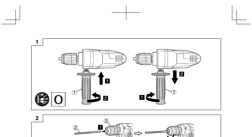
- Fixing/removing side handle: Fig 1
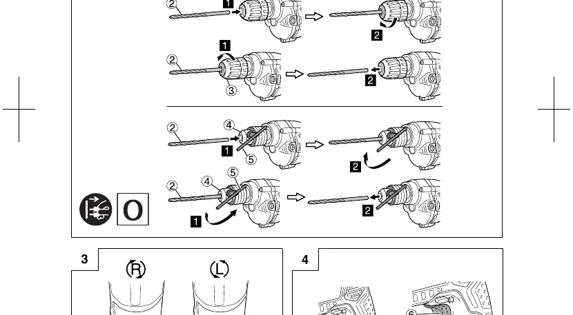
- Mounting/dismounting the bit: Fig 2
- Selecting rotational direction: Fig 3
- Switch operation: Fig 4
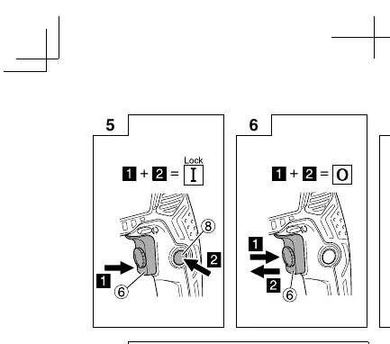
- Locking/releasing the switch: Fig 5, 6
- Adjusting trigger pull distance: Fig 7
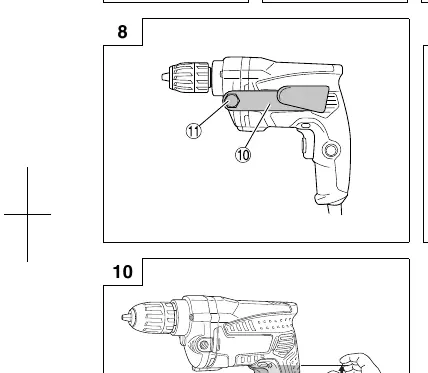
- Mounting hook: Fig 8, 9
Drilling
Start drilling slowly and increase speed gradually. Apply pressure in a straight line with the bit. Do not apply excessive pressure to avoid stalling the motor or bending the bit. If the drill stalls, release the trigger immediately and remove the bit from the workpiece.
Maintenance and Inspection
- Inspecting drill bits: Replace or resharpen abraded bits immediately.
- Inspecting mounting screws: Regularly check and tighten all screws.
- Motor maintenance: Keep the motor winding clean and free from oil or water.
- Carbon brushes: Inspection and replacement must be performed by a HiKOKI Authorized Service Center.
Manufacturer information
HiKOKI
Practical help
Common problems
Drill stalls
Release trigger immediately, remove bit from work, and start again. Do not click trigger on/off.
Drill bit overheats
Do not cool in water or oil. It is operable.
Hook slips
Ensure hook is not deformed and is correctly positioned.
Before use
- Check that power source conforms to nameplate requirements.
- Ensure power switch is in OFF position before plugging in.
- Check that work area is free of hidden cables or conduits.
- Ensure side handle is securely fixed.
- Wear eye protection.
Specs in practice
- No load speed
- 0 – 2500 min–1
- Drill chuck capacity
- 10 mm
- Capacity (Steel)
- 10 mm
- Capacity (Wood)
- 32 mm (Flat Spade Bit), 25 mm (Auger Bit)
Images and diagrams
- Fig 1: Fixing/removing side handle.
- Fig 2: Mounting/dismounting the bit.
- Fig 3: Selecting rotational direction.
- Fig 4-6: Switch operation and locking.
- Fig 8-9: Hook mounting positions.
Model compatibility
- Use metalworking bits for metal/plastic.
- Use woodworking bits for wood.
- For holes 6.5mm or smaller in wood, use a metalworking bit.

Manual page author
David Miller
Documentation analyst
Organizes user manual content into clear summaries, with attention to model details, product context, and everyday usability.